


Page 23
SERVICE (cont.)
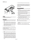
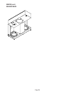
RELAY
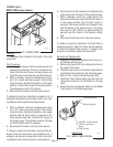
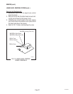
FIG. 16 RELAY
P2172.80
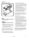
Location:
The relay is located in the right rear corner of the
hood.
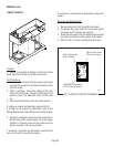
Test Procedures
1. Disconnect the brewer from the power source.
2. With a voltmeter, check the voltage across termi-
nals A & B in the lower corners of the relay when
the On/Left switch is in the upper position and the
Start switch is pressed to the lower position and
released. Connect the brewer to the power source.
The indication must be 120 volts ac for the ap-
proximate setting on the brew timer dial and then
return to zero.
3. Disconnect the brewer from the power source.
If voltage is present as described, proceed to #4.
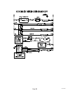
If voltage is not present as described, refer to the
Wiring Diagram
and check the brewer wiring harness.
4. Remove the black and white wires from terminals
A & B.
5. Check for continuity across terminals A & B of the
relay.
If continuity is present as described, reconnect the
black and white wires and proceed to #6.
If continuity is not present as described, replace the
relay.
6. Remove the white/brown, white/red, and white/
blue wires from terminals 2, 5 & 7 of the relay.
10179 060100
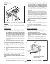
7. Check for continuity across terminals 2 & 7 when
the On/Left switch is in the upper position only
until the Start switch is pressed to the lower posi-
tion and released. Connect the brewer to the power
source. Continuity must return across these ter-
minals after the approximate setting on the brew
timer dial.
8. Disconnect the brewer from the power source.
9. Check for continuity across terminals 5 & 7 when
the On/Left switch is in the upper position and the
Start switch is pressed to the lower position and
released. Connect the brewer to the power source.
Continuity must be present across these termi-
nals for the approximate setting on the brew timer
dial.
10. Unplug the brewer.
If continuity is present as described, reconnect the
wires, the relay is operating properly.
If continuity is not present as described, replace the
relay.
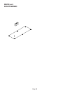
Removal and Replacement:
1. Remove all wires from the relay terminals.
2. Remove the two #8-32 nuts holding the relay
mounting bracket to the hood.
3. Remove the relay from the mounting bracket.
4. Securely install the new relay to the mounting
bracket.
5. Install the relay mounting bracket to the hood.
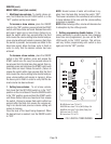
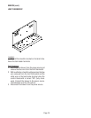
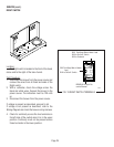
6. Refer to FIG. 17 when reconnecting the wires.
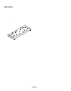
FIG. 17 RELAY TERMINALS
P1988
BLK to Timer
WHI/BRN to Liquid Level l
Board
WHI/RED toLiquid Level Board
WHI/RED to Timer
WHI/BLU to
Solenoid
WHI to Timer
7
2
5