TROUBLESHOOTING
Complete Unit Stoppage and Restart —
Pos-
sible causes for unit stoppage and reset methods are (also
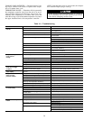
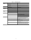
see Table 14):
GENERAL POWER FAILURE — After power is restored,
restart is automatic through the normal timer cycle.
UNIT ON-OFF SWITCH IS OPEN — When the switch is
opened, the unit stops immediately. If the switch is closed
immediately after it was opened, the unit restarts automati-
cally after the 5-minute timer cycle is completed. If the switch
is closed after an extended off-period, the unit restarts au-
tomatically in approximately 3 seconds.
CONTACTS OF ANY AUXILIARY INTERLOCKS ARE
OPEN — After the problem has been corrected, restart is
automatic after completion of the 5-minute timer cycle.
CHILLED FLUID PROOF-OF-FLOWSWITCH(ES) OPEN
— After the problem causing the loss of flow has been cor-
rected, restart is automatic after completion of the 5-minute
timer cycle.
OPEN LOW-PRESSURE SWITCH — If a low-pressure switch
remains open for more than 2 minutes during unit operation,
the compressor(s) shuts down and is locked off. The unit ser-
vice light is illuminated. Determine and correct the cause of
the failure. The switch automatically resets, but the unit must
be manually reset by cycling the unit control power (move
the ON-OFF switch to OFF, then to ON). The unit restarts
after completion of the 5-minute timer cycle unless the re-
frigerant charge is either very low or lost. If this is the case,
determine the cause of the loss of charge, correct the prob-
lem, and recharge the unit before restarting.
TEMPERATURE CONTROLLER SHUTS UNIT DOWN
ON OUT-OF-RANGE (See Fig. 21) — Check the ther-
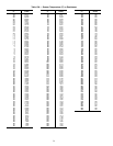
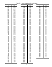
mistor for an open circuit failure. See Tables 12A and 12B
for temperature-resistance values. If thermistor is damaged,
replace it. If thermistor is not damaged, the unit restarts
automatically after completion of the 5-minute timer cycle,
and after the leaving cooler chilled fluid temperature
rises above the upper deadband limit of the temperature
controller.
OPEN HIGH-PRESSURE SWITCH(ES) — The unit ser-
vice light is illuminated. Determine and correct the cause of
the failure. The switch(es) automatically resets but the unit
must be manually reset by cycling the control power (move
ON-OFF switch to OFF, then back to ON). The unit restarts
after completion of 5-minute timer cycle.
OPEN COMPRESSOR INTERNALTHERMAL PROTEC-
TION (30HW UNITS) — This is compressor overtempera-
ture protector on 30HW018 units and the discharge gas ther-
mostat (DGT) on 30HW025-040 units. The unit service light
is illuminated. Determine and correct cause of problem. The
switch resets automatically but unit must be reset by cycling
the control power (move ON-OFF switch to OFF, then back
to ON). The unit restarts after completion of 5-minute timer
cycle.
OPEN OIL PRESSURE SWITCH — If oil pressure switch(es)
opens for more than 2 minutes during unit operation, the unit
shuts down and is locked off. The unit service light is illu-
minated. Determine and correct cause of failure. Unit must
be reset by cycling the control power (move ON-OFF switch
to OFF, then back to ON). Unit restarts after completion of
5-minute timer cycle.
OPEN CONTACTS ON COMPRESSOR GROUND-
CURRENT SENSOR(S) (Accessory) — The light-emitting
diode (LED) on the ground current accessory board (located
in field control wiring section of control box) is illuminated.
See Fig. 17-20. Unit service light is also illuminated. Check
the compressor motor windings for a short to ground.
Determine and correct cause of the failure. The unit must be
reset by cycling the control power (move ON-OFF switch to
OFF, then back to ON). Unit restarts after completion of the
5-minute timer cycle.
OPEN 24-V CONTROL CIRCUIT BREAKER(S) — De-
termine the cause of the failure and correct. Reset circuit
breaker(s). Restart is automatic after completion of 5-minute
timer cycle.
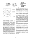
Fig. 24 — Elliott Tube Plug
HEAD BOLT TIGHTENING SEQUENCE
Fig. 25 — Typical Tube Sheet
37


