10
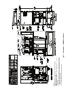
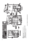
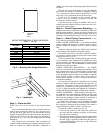
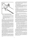
3. Install the inside coupling half over the gasket and then
install the outer half. Connect with nuts and bolts. Tighten
the nuts equally on both sides. Ensure there is no gap be-
tween the two halves of the coupling.
4. Alternately tighten the nuts with a wrench to draw the
coupling halves together uniformly. The joint is now
complete.
30MPW UNITS — In order to minimize the water pressure
drop in the system, use as few bends as possible in the field
water piping, and run the lines as short as possible. Size the
water lines according to the available pump pressure (not neces-
sarily the connection size), especially on cooling tower applica-
tions. See Carrier System Design Manual, Part 3, Piping Design.
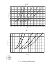
See Fig. 11 for condenser pressure drops.
Set water regulating valve, if installed, to maintain design
head pressure. Do not adjust to compensate for high head pres-
sures caused by fouled condensers, excess refrigerant, or the
presence of noncondensables. Due to changes in water temper-
ature, it may be necessary to adjust the valve seasonally. After
adjusting for design head pressure, shut unit down. The water
regulating valve should shut off the flow of water in a few min-
utes. If it does not, raise head pressure setting. Make sure that
the capillary tube from each water regulating valve is connect-
ed to the proper condenser access fitting.
Provide a means for draining the system in the winter (if not
used) and for maintenance.
Water leaving the condenser is under pressure and should
not be connected directly into sewer lines. Check local codes.
EVAPORATOR DESCRIPTION — All 30MP units use a
brazed-plate heat-exchanger type evaporator. The heat ex-
changer is constructed essentially the same as the brazed-plate
condenser used on 30MPW units. See 30MPW Condenser De-
scription section on page 7 for more details. Similar to the con-
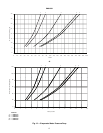
denser, the evaporator can only be chemically cleaned. See Fig.
12 for evaporator pressure drops.
EVAPORATOR PIPING — Plan evaporator fluid piping for
minimum number of changes in elevation, and for the fewest
number of bends possible. Install manual or automatic vent
valve at high points in the line. Maintain system pressure by
using a pressure tank or a combination of relief and reducing
valves.
A strainer with a minimum of 40 mesh must be installed
within 10 ft of the evaporator fluid inlet to prevent debris from
clogging or damaging the heat exchanger. This strainer is re-
quired and is available as an accessory.
See Carrier System Design Manual, Part 3, Piping Design,
for chilled fluid piping details.
The evaporator fluid inlet and outlet connections are vict-
ualic. The fluid enters at the top connection and leaves at the
bottom connection. Procedures for making the connections are
the same as for the 30MPW condensers. See 30MPW Con-
denser section on page 7 for more details.
Run the pump for 10 minutes, then clean the strainer before
starting the unit.
An evaporator flow switch is standard on all units. This is a
thermal dispersion type switch that is installed in the evapora-
tor fluid outlet. The switch is set to open when the evaporator
fluid flow drops below the minimum set point.
For variable primary flow applications, it may be necessary
to adjust the flow switch set point to avoid nuisance trips. Con-
tact Carrier service engineering for the mthod needed to adjust
the switch.
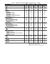
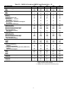
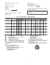
See Table 1 for minimum flow rates and loop volume.
The thermistors used to sense entering and leaving fluid
temperature are factory-installed in the evaporator entering and
leaving fluid nozzles.
AIR SEPARATION — For proper system operation, it is
essential that water loops be installed with proper means to
manage air in the system. Free air in the system can cause
noise, reduce terminal output, stop flow, or even cause pump
failure due to pump cavitation. For closed systems, equipment
should be provided to eliminate all air from the system.
The amount of air that water can hold in solution depends
on the pressure and temperature of the water/air mixture. Air is
less soluble at higher temperatures and at lower pressures.
Therefore, separation can best be done at the point of highest
water temperature and lowest pressure. Typically, this point
would be on the suction side of the pump as the water is return-
ing from the system or terminals. Generally speaking, this is
the best place to install an air separator, if possible.
1. Install automatic air vents at all high points in the system.
(If the 30MP unit is located at the high point of the
system, a vent can be installed on the piping entering the
heat exchanger on the ¼-in. NPT female port.)
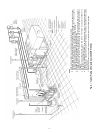
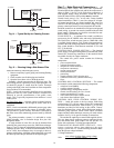
2. Install an air separator in the water loop, at the place
where the water is at higher temperatures and lower
pressures — usually in the chilled water return piping.
On a primary-secondary system, the highest temperature
water is normally in the secondary loop, close to the
decoupler. Preference should be given to that point on the
system (see Fig. 13). In-line or centrifugal air separators
are readily available in the field.
It may not be possible to install air separators at the place of
lowest pressure and highest temperature. In such cases, prefer-
ence should be given to the points of highest temperature. It is
important that pipe be sized correctly so that free air can be
moved to the point of separation. Generally, a water velocity of
at least 2 feet per second will keep free air entrained and
prevent it from forming air pockets.
Automatic vents should be installed at all physically elevat-
ed points in the system so that air can be eliminated during
system operation. Provision should also be made for manual
venting during the water loop fill. It is important that the
automatic vents be located in accessible locations for
maintenance purposes, and that they be located where they can
be prevented from freezing.
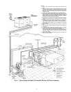
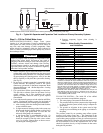
Fig. 10 — Install the Victualic Coupling
a30-1245