


7
Step 3 — Place the Unit
NOTE: These units are not suitable for unprotected outdoor
use.
Carrier recommends that these units be located in the base-
ment or on the ground floor. However, if it is necessary to lo-
cate the unit on an upper floor, be sure the structure has been
designed to support the unit weight. If necessary, add structural
support to floor. Also, be sure the surface for installation is
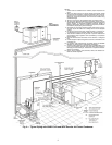
level. Refer to Fig. 4 and 5 for space requirements and weight
distribution.
Only electrical power connections, water connections for
condenser, fluid connections for evaporator, and strainer instal-
lation are required for 30MPW installation. Installation of
30MPA units varies only in field piping required for the remote
condenser.
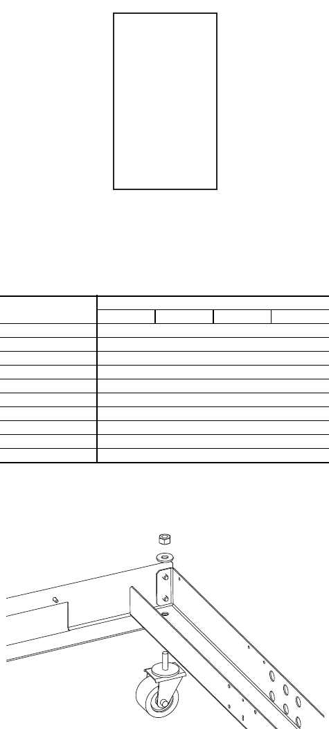
When the unit is in its final position, remove the packaging
and remove the mobility kit wheels (if equipped). Remove
3
/
8
-in. wheel nuts to remove wheels from unit legs. Level the
unit (using a level), and bolt the unit to the floor or pad.
If unit is to be mounted on unit external vibration
isolators, follow the mounting instructions included with
the accessory vibration isolator.
If unit has accessory leveling kit installed, follow the in-
structions provided with the accessory to make sure unit is lev-
el and in the correct position.
Step 4 — Check Compressor Mounting — As
shipped, units with two compressors are held down with 6 bolts
through rubber grommets. All units with three compresors are
held down with 8 bolts per pair through grommets. After unit is
installed, verify mounting bolt torque 7 to10 ft-lb (9 to 14 Nm).
Step 5 — Make Piping Connections — See
Fig. 8 and 9 for typical piping applications.
30MPA SYSTEM CONDENSER — For detailed condenser
piping installation instructions for 30MPA systems, refer to
separate instructions packaged with the remote condenser
units.
Condenser refrigerant piping for 30MPA units should be
sized to minimize the amount of refrigerant required.
The 30MPA units that use air-cooled evaporative condens-
ers must have adequate means for head pressure control when
operating below 60 F (15.6 C).
Carrier recommends that a field-supplied pressure relief de-
vice be installed in each discharge line of 30MPA units. Most
local codes require the discharge line relief valve to be vented
directly to the outdoors. The vent must not be smaller than the
discharge line relief valve outlet.
30MPW CONDENSER DESCRIPTION — All 30MPW
units use a brazed-plate heat-exchanger-type condenser. These
heat exchangers are made of embossed plates of acid-resistant
stainless steel. Every other plate is reversed so that the ridges
of the herringbone pattern intersect one another on adjacent
plates, forming a lattice of contact points. These plates are
vacuum-brazed together to form a compact and pressure-
resistant heat exchanger.
After brazing, the impressions in the plates form 2 separate
systems of channels where the refrigerant and water flows are
counterflow. The number of plates varies depending on unit
tonnage. The condensers provide approximately 10º to 12º F
(6º to 8º C) liquid subcooling at the standard Air Conditioning,
Heating and Refrigeration Institute (AHRI) rating condition.
30MPW CONDENSER — When facing the unit control box,
the condenser is the uninsulated heat exchanger located on the
left-hand side. The water connections are on the right-hand
side of the heat exchanger with the LIQUID-IN connection at
the bottom, and the LIQUID-OUT connection at the top.
A strainer with a minimum of 40 mesh must be installed
within 10 ft (3 m) of the condenser water inlet to prevent debris
from clogging or damaging the heat exchanger. The strainer is
required for operation and is available as an accessory.
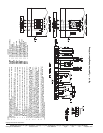
To install the victaulic coupling (see Fig. 10):
1. Lubricate the gasket lips and stretch the gasket over
the end of the heat exchanger coupling. Avoid twisting
the gasket when installing.
2. Bring the pipe and heat exchanger coupling ends together
into alignment. Slide the gasket so that it is centered over
the ends. Apply a light film of lubricant to the gasket, or
to the outside diameter of the pipe. Avoid twisting the
gasket during installation.
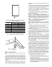
B
A
C
D
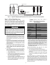
CONTROL
PANEL
SIDE
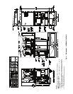
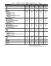
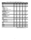
WEIGHT DISTRIBUTION AT EACH MOUNTING
HOLE — Lb (kg)
UNIT 30MP
MOUNTING HOLE
ABCD
A015 156 (71)
A020 159 (72)
A030 181 (82)
A040 228 (104)
A045 234 (106)
W015 170 (77)
W020 176 (80)
W030 216 (98)
W040 275 (125)
W045 298 (135)
Fig. 6 — Mounting Hole Weight Distribution
a30-5040
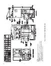
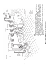
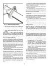
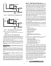
Fig. 7 — Mobility Kit
a30-5041