


2
INSTALLATION
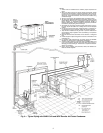
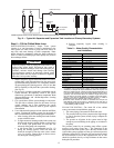
Location —
Do not store units in an area exposed to weath-
er because of sensitive control mechanisms and electronic
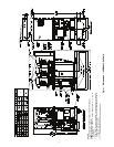
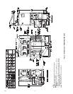
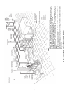
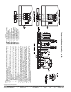
devices. Locate unit indoors. See Fig. 4 and 5 for unit dimen-
sional details.
When considering location, consult National Electrical
Code (NEC) and local code requirements. Allow sufficient
space for wiring, piping, and service. Install unit in an area
where it will not be exposed to ambient temperatures below
50 F (10 C).
Allow 36 in. (914 mm) in front of the unit for control box
access door. Additional clearance may be required per local
codes. Prior to installation determine which direction compres-
sor will be removed, and leave 3 to 4 ft (914 to 1219 mm)
clearance for removal.
On all units leave 3 ft (0.9 m) of clearance behind the unit to
make water/brine connections to the evaporator, accessing the
TXV (thermostatic expansion valve), fluid thermistors, and
proof of flow switch.
On all units, leave 2 ft (610 mm) on one side for making re-
frigeration connections (30MPA) or fluid connections
(30MPW) to condenser. See Fig. 4 and 5.
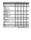
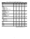
The floor must be strong enough to support the unit operat-
ing weight (see Tables 1A and 1B and Fig. 4-6). If necessary,
add a supporting structure (steel beams or reinforced concrete
slabs) to the floor to transfer weight to nearest beams.
Additional weight of factory-installed sound enclosure op-
tion is 75 lb (34 kg).
Step 1 — Inspect Shipment — Inspect unit for dam-
age or missing parts. If damaged, or if shipment is incomplete,
file a claim immediately with the shipping company.
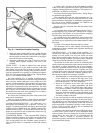
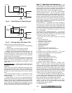
Step 2 — Position the Unit — The unit may be
moved by means of rollers under the rails or a forklift truck.
If accessory mobility kit is to be used, install this accessory
after bringing unit into building and before moving the unit to
its final location per installation instructions provided with the
accessory. The factory-installed mobility kit option consists of
4 swivel-type wheels that are field-mounted to the legs of the
unit. See Fig. 7.
NOTE: The wheels are equipped with a thumb-screw brake.
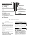
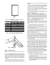
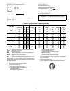
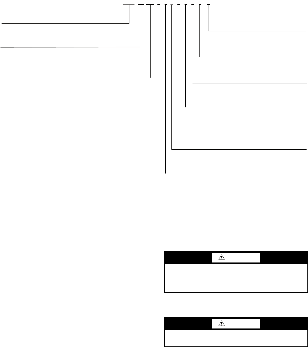
30MP
A0306 -
30MP – Aquasnap® Liquid Chiller with ComfortLink™ Controls
Condenser Option
A – Chiller without Condenser (Air-Cooled)
Design Revision Level
W – Chiller with Condenser (Water-Cooled)
- – Initial Release
Voltage Options
1 – 575-3-60
5 – 208/230-3-60
6 – 460-3-60
Unit Size – Nominal Tons (kW)
015 – 15 (54) 040 – 40 (138)
020 – 20 (71) 045 – 45 (161)
030 – 30 (108)
2 – 380-3-60
0
Sound/Mounting Options
0 – None
1 – S
ound Enclosure Panels
3 – Height Adjustment Kit
4 – Height Adjustment Kit, Sound Enclosure Panels
9 – Mobility Kit (Wheels)
B – Mobility Kit (Wheels), Sound Enclosure Panels
D – Height Adjustment Kit, Mobility Kit (Wheels)
F – Height Adjustment Kit, Mobility Kit (Wheels), Sound Enclosure Panels
0
Comfort Cooling/Medium Temp Brine Options
0 – Comfort Cooling Duty (32-60 F) (Std)
7 – Medium Temperature Brine (15-32 F)
0
Capacity Control Options
0 – Standard
1 – Hot Gas Byp
ass
0
Disconnect Options
0 – Standard (Terminal Block)
1 – Non-Fused Disconnect Switch
0
Controls/Interface Options
0 – Scrolling Marquee Display (Std)
5 – Scrolling Marquee Display, EMM
5
Packaging Options
5 – Bag
B – Export Crate
Fig. 3 — 30MP Model Number Nomenclature
LEGEND
EMM — Energy Management Module
LON — Local Operating Network
UPC — Unitary Protocol Controller
a30-5038
CAUTION
Be sure interconnecting piping and electrical conduits
are suspended freely, and are not in contact with any
adjacent walls. Be sure unit capillaries are not rubbing
against anything. Damage to unit or walls may result.
CAUTION
Unit is top heavy. Unit may tip if handled without care.
Damage to unit or injury may result.