


Manufacturer reserves the right to discontinue, or change at any time, specifications or designs without notice and without incurring obligations.
Catalog No. 04-53300054-01 Printed in U.S.A. Form 30MP-1SI Pg 16 910 1-10 Replaces: New
Copyright 2010 Carrier Corporation
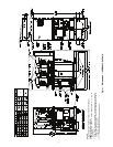
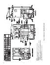
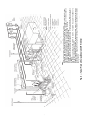
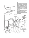
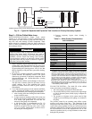
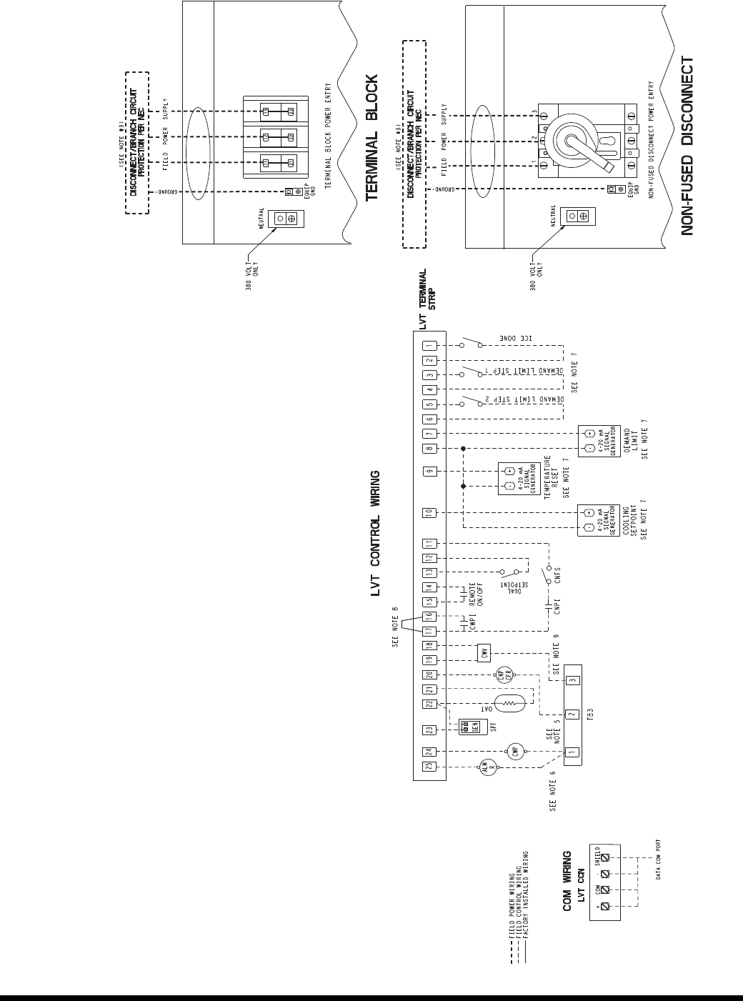
Fig. 16 — Typical Low Voltage Control Wiring
NOTES:
1. Factory wiring is in accordance with UL 1995 standards. Field modifications or additions must be in
compliance with all applicable codes.
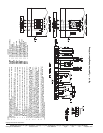
2. All units or modules have single point primary power connection. Main power must be supplied
from a field or factory supplied disconnect.
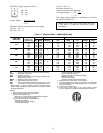
3. Wiring for main field supply must be rated 75 C. Use copper conductors only.
a. Incoming wire size range for terminal block with MCA up to 120 amps is 14 AWG (American
Wire Gage) to 2/0.
b. Incoming wire size range for terminal block with MCA from 120.1 amps to 310 amps is 6 AWG
to 350 kcmil.
c. Incoming wire size range for non-fused disconnect with MCA up to 50 amps is 10 AWG to
2 AWG.
d. Incoming wire size range for non-fused disconnect with MCA from 50.1 amps to 90 amps is 6
AWG to 3/0.
e. Incoming wire size range for non-fused disconnect with MCA from 90.1 amps to 250 amps is 4
AWG to 350 kcmil.
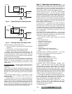
4. Refer to certified dimensional drawings for exact locations of the main power and control power
entrance locations.
5. Terminal 24 of the LVT is for controlof chilled water pump (CWP) starter. Terminal 20 of the LVT is
for control of condenser pump (CNP) starter or condenser fan relay (CFR). The maximum load
allowed for the relays is 5 VA sealed. 10 VA inrush at 24 VAC. Field power supply is required.
6. Terminal 25 of LVT is for an alarm relay. The maximum load allowed for alarm relay is 5 VA sealed,
10 VA inrush at 24 VAC. Field power supply is not required.
7. Make approprate connections to LVT as shown for energy management board options. The con-
tacts for demand limit and ice done options must be rated for dry circuit application capable of han-
dling 24 VAC load up to 50 mA. Installation of optional energy management board required.
8. Remove jumper between terminals 16 and 17 when field chilled water pump interlock (CWPI) is
installed.
9. Terminals 18 and 19 of LVT are for floating point control of condenser water valve (CWV). Teminal
18 commands valve closed. Terminal 19 commands valve open. The maximum load allowed for
condenser water valve is 5.5 VA at 24 VAC. Field power supply is not required.
10. All discrete inputs are 24 VAC.
LEGEND
ALMR — Alarm Relay (24 V) 5 VA Max
AWG — American Wire Gage
CFR — Condenser Fan Relay
CNFS — Condenser Flow Switch
CNP — Condenser Pump
CNPI — Condenser Pump Interlock
CWP — Chilled Water Pump
CWPI — Chilled Water Pump Interlock
CWV — Condenser Water Valve
EMM — Energy Management Module
LVT — Low Voltage Terminal Strip
NEC — National Electrical Code
OAT — Outside Air Temperature
SPT — Space Temperature
a30-5039