


9
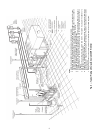
NOTES:
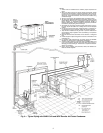
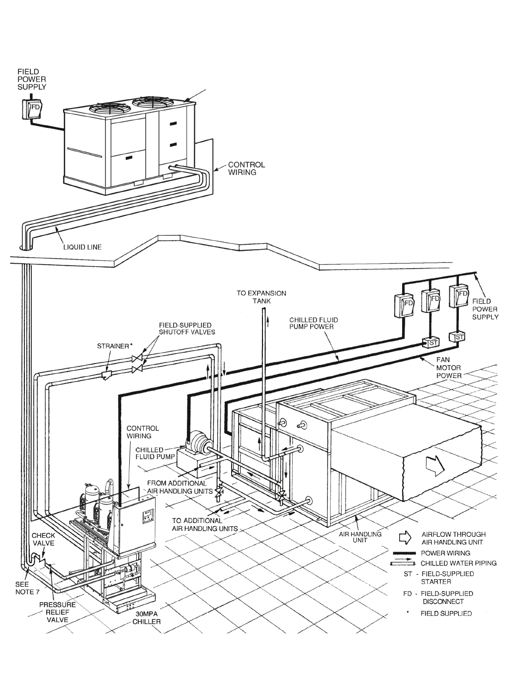
1. Chiller must be installed level to maintain proper compressor oil
return.
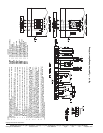
2. Wiring and piping shown are general points-of-connection guides
only and are not intended for a specific installation. Wiring and pip-
ing shown are for a quick overview of system and are not in accor-
dance with recognized standards. Units should be installed using
certified drawings.
3. All wiring must comply with applicable local and national codes.
4. All piping must follow standard piping techniques. Refer to Carrier
System Design Manual part 3, Carrier E20-II software Refrigerant
Piping program, or appropriate ASHRAE (American Society of
Heating, Refrigerating, and Air Conditioning Engineers) handbook
for details on proper piping sizes and design.
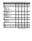
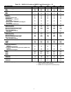
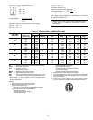
5. See Tables 1A and 1B for minimum system fluid volume. This sys-
tem may require the addition of a holding tank to ensure adequate
volume.
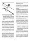
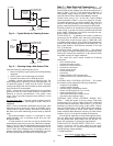
6. Hot gas lines should rise above refrigerant level in condenser cir-
cuit. Double riser may be required; check unit minimum capacity.
7. Trap should be installed on hot gas lines to prevent condenser oil
and refrigerant vapor migration from accumulating in compressor
during off cycle.
8. Pitch all horizontal lines downward in the direction of refrigerant
flow.
9. Provide support to liquid and gas lines near the connections to the
condenser coil.
10. For pressure relief requirements, see latest revision of ASHRAE
Standard 15, Safety Code for Mechanical Refrigeration.
11. A strainer with a minimum of 40 mesh must be installed within 10 ft
(3 m) of the evaporator fluid inlet to prevent debris from clogging or
damaging the heat exchanger. This strainer is required and is avail-
able as an accessory.
12. Piping, wiring, switches, vents, strainers, drains, and vibration iso-
lation are all field-supplied.
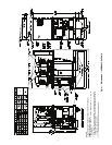
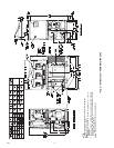
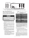
Fig. 9 — Typical Piping with 30MPA Unit and 09DP Remote Air-Cooled Condenser
09DP
AIR-COOLED
CONDENSER
a30-4998