


14
Ensure the following when filling the system:
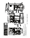
1. Remove temporary bypass piping and cleaning/flushing
equipment.
2. Check to make sure all drain plugs are installed.
3. Open the blow-down valve to flush the strainer.
Normally, a closed system needs to be filled only once. The
actual filling process is generally a fairly simple procedure. All
air should be purged or vented from the system. Thorough
venting at the high points and circulation at room temperature
for several hours is recommended.
NOTE: Local codes concerning backflow devices and other
protection of the city water system should be consulted and
followed to prevent contamination of the public water
supply. This is especially important when antifreeze is used
in the system.
Set Water Flow Rate
— Once the system is cleaned, pressur-
ized, and filled, the flow rate through the chiller needs to be
established.
NOTE: Carrier recommends a differential pressure gage when
measuring pressures across the pumps or balancing valves.
This provides for greater accuracy and reduces error build-up
that often occurs when subtracting pressures made by different
gages.
On primary/secondary systems, it is advisable to set the
30MP balancing valve to maintain design flow plus 10%
through the chiller.
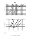
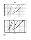
A rough estimate of water flow can also be obtained from
measuring the pressure drop across the 30MP heat exchanger.
Figures 11 and 12 show the relationship between gpm and heat
exchanger pressure drop. It should be noted that these curves
are for “clean” heat exchangers; they do not apply to heat ex-
changers with fouling. Adjust the external balancing valve until
the correct pressure drop is obtained for the required gpm.
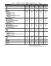
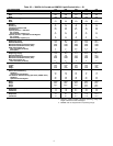
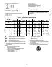
Step 7 — Make Electrical Connections — All
field wiring must comply with local code requirements.
Electrical data for the complete unit and for the compressors is
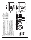
shown in Table 3. See Fig. 16 for field wiring connections. A
field-supplied branch circuit disconnect switch that can be
locked in either OPEN or OFF position must be installed.
Control circuit power is 24 v on all units. Factory-installed
control transformer (TRAN 1) uses line voltage for all units.
All control transformers are factory-installed and wired. For
208/230-3-60 units operating at 208-3-60 line voltage, TRAN1
primary connections must be moved to terminals H3 and H4.
Inside the control box are terminals for field power and ground
(earth) wiring. A ground wire must be installed with each field
power supply. Compressors are wired for across-the-line start.
Refer to Table 3 for electrical data.
FLOW SWITCH — A condenser flow switch is available as
an accessory for all 30MPW units, and can be field-installed.
The Carrier flow switch accessory (part no. 30MP-900---004)
is available for this purpose. Flow switch wiring terminals are
located in the field wiring compartment of the control box. The
flow switch should be wired between terminals LVT-16 and
LVT-17 for all units.
CONTROL BOX, POWER SECTION — The electrical
power supply is brought in through the top left-hand side of the
control box. Pressure-lug connections on the terminal blocks
are suitable for only for copper conductors.
The control box power section contains the following
components:
• power terminal block
• optional disconnect switch
• compressor circuit breaker(s)
• compressor contactor(s)
• current sensor boards
• control transformer
• ground lug
• neutral terminal (380-3-60 units only)
• crankcase heater relay (30MPA units only)
•fuses
CONTROL BOX, CONTROLS SECTION — The control
box controls section contains the following components:
• main base board (MBB)
• scrolling marquee display
• optional energy management module
• control-circuit breakers for 24-v circuits
• control-circuit ON-OFF switch
• unit Enable/Off/Remote contact switch
• unit Alarm/Alert indicator light
CONTROL BOX, FIELD CONTROL WIRING SEC-
TION — Inside this section is the low-voltage, field-wiring
terminal strip (LVT). All low-voltage field-wiring connections
are made to this terminal block. There are three
7
/
8
-in. (22 mm)
knockouts provided for field wiring in this section. Connec-
tions for condenser flow switch, chilled fluid pump interlock,
condenser pump interlock, remote alarm output, condenser
output, and dual chiller thermistor accessory are made at these
locations. See Fig. 16 for specific location of connections.
The unit has the capability to control field-supplied devices.
They are: alarm signal, condenser pump or condenser fan out-
put, and chilled water pump output. The unit provide 24-v
power with a minimum 5 va rating per output allowed.
UNBALANCED 3-PHASE SUPPLY VOLTAGE — Never
operate a compressor where a phase imbalance in the supply
voltage is greater than 2%. Use the following formula to deter-
mine the percent voltage imbalance:
% Voltage Imbalance =
100 x
max voltage deviation from average voltage
average voltage
x
x
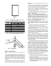
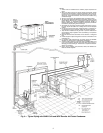
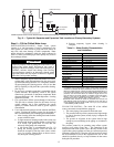
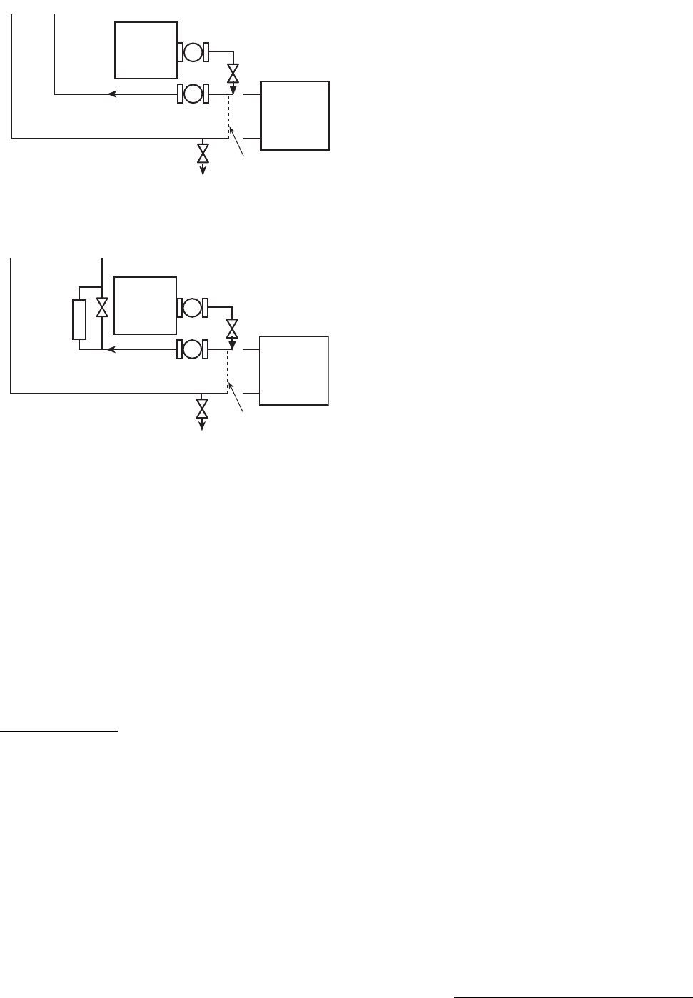
DILUTED
CLEANING
AGENT
SYSTEM
POT FEEDER AND
TRANSFER PUMP
30MPUNIT
TO DRAIN
TEMPORARY
PUMP
TEMPORARY
BYPASS
Fig. 14 — Typical Set Up for Cleaning Process
a30-5047
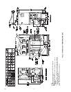
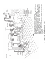
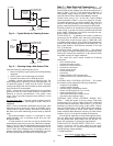
x
x
DILUTED
CLEANING
AGENT
SYSTEM
SIDE
STREAM
FILTER
POT FEEDER AND
TRANSFER PUMP
30MPUNIT
TO DRAIN
TEMPORARY
PUMP
TEMPORARY
BYPASS
Fig. 15 — Cleaning Using a Side Stream Filter
a30-5048