


23
Variable evaporator flow rates
Variable flow rates may be applied to a standard chiller.
The unit will, however, attempt to maintain a constant
leaving fluid temperature. In such cases minimum flow
must be in excess of minimum flow given in the
Evaporator and Condenser Flow Rates table, and mini-
mum loop volume must be in excess of 3 gallons per ton
(3.21 L per kW). Combined flow rate and change in load
must not change by more than 10% per minute. Additional
loop volume may be necessary to ensure fluid is not quickly
recirculated back to the chiller before the chiller has
adjusted to the previous change in flow rate and load
condition.
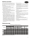
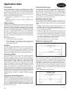
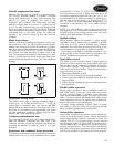
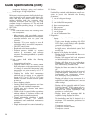
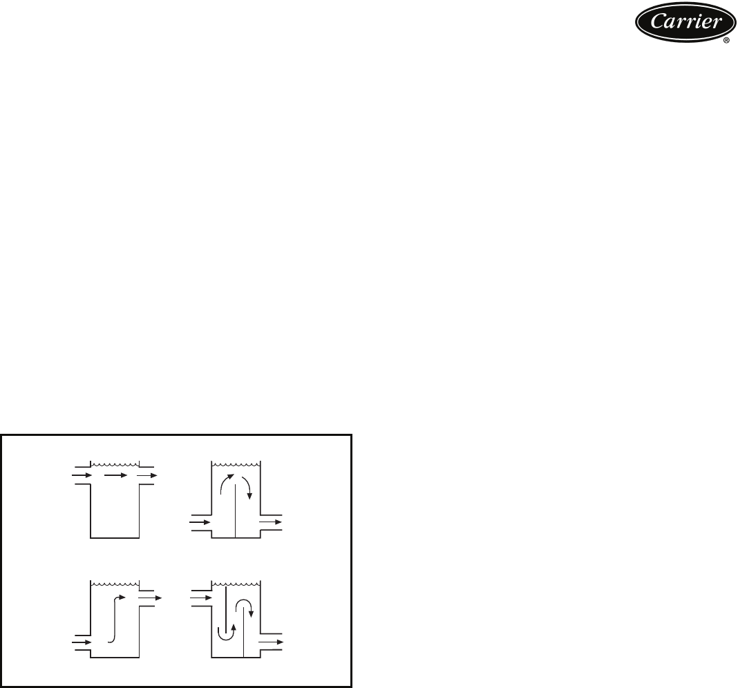
Water loop volume
The loop volume in circulation must equal or exceed 3 gal.
per nominal ton (3.2 L per kW) of cooling for temperature
stability and accuracy in normal air-conditioning applica-
tions. In process cooling applications, there should be 6 to
10 gallons per ton (6.5 to 10.8 L per kW). To achieve this
loop volume, it is often necessary to install a tank in the
loop. The tank should be baffled to ensure there is no strat-
ification, and that water (or brine) entering the tank is ade-
quately mixed with liquid in the tank. See Tank installation
drawing.
Evaporator fouling factor
The fouling factor used to calculate tabulated ratings is
0.0001 sq ft hr F/Btu (0.000018 sq m C/W). As
fouling factor is increased, both unit capacity and EER
(Energy Efficiency Ratio) decrease. The impact of the foul-
ing factor on performance varies significantly with chiller
size and application conditions. Ratings must be deter-
mined by the Carrier selection program.
Condenser minimum flow rate
The minimum condenser flow rate is shown in the Mini-
mum and Maximum Condenser Flow Rate Table. If the
condenser flow rate is below the minimum rate shown, try
increasing the number of condenser passes (1 or 2 pass
available).
Evaporator and condenser freeze protection
The solution concentration must be sufficient to protect the
chilled water loop to a freeze protection (first crystals)
concentration of at least 15 F (8.3 C) below the leaving
fluid temperature set point. If chiller fluid lines are in an
area where ambient conditions fall below 34 F (1.1 C), it is
recommended that an antifreeze solution be added to pro-
tect the unit and fluid piping to a temperature 15 F
(8.3 C) below the lowest anticipated temperature. For
corrections to performance, refer to the chiller selection
program.
NOTE: Use only antifreeze solutions approved for heat
exchanger duty. Use of automotive antifreeze is not recom-
mended because of the fouling that can occur once their
relatively short-lived inhibitors break down.
Multiple chillers
Where multiple chillers are required, or where standby
capability is desired, chillers may be installed in parallel.
Units may be of the same or different sizes. However,
evaporator flow rates must be balanced according to the
recommendations of each chiller to ensure proper flow.
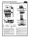
Unit software is capable of controlling two units as a sin-
gle plant. Refer to the Controls, Start-Up, Operation, Ser-
vice and Troubleshooting guide for further details.
Dual chiller control
The chiller on board controller allows 2 chillers (piped in
parallel or series) to operate as a single chilled water plant
with standard control functions coordinated through the
master chiller controller. This feature requires a communi-
cation link between the 2 chillers. There are several advan-
tages to this type of control:
• Redundancy (multiple circuits)
• Better low load control (lower tonnage capability)
• Lower rigging lift weights (2 machines rather than one
large machine)
• Chiller lead-lag operation (evens the wear between the
two machines)
Parallel chiller operation
Parallel chiller operation is the recommended option for
dual chiller control. In this case, each chiller must control
its own dedicated pumps or isolation valves. Balancing
valves are recommended to ensure the proper flow to each
chiller. Two field-supplied and installed dual chiller leaving
water temperature sensors are required (one for each mod-
ule) for this function to operate properly.
Consider adding additional isolation valves to isolate
each chiller to allow for service on the machine, and still
allow for partial capacity from the other chiller.
Series chiller operation
Series chiller operation is an alternate control method sup-
ported by the chiller control system. Certain applications
might require that two chillers be connected in series. For
nominal 10 F (5.6 C) evaporator ranges, use the one-pass
heat exchanger options to reduce fluid side pressure drop.
Use the standard pass arrangement for low flow, high tem-
perature rise applications. Two field-supplied and installed
dual chiller leaving water temperature sensors are required
(one for each module) for this function to operate properly.
⋅
°
⋅
°
°
°
°
°
BAD
BAD
GOOD
GOOD
TANK INSTALLATION
a30-3185