


25
Typical piping and wiring
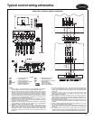
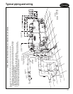
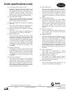
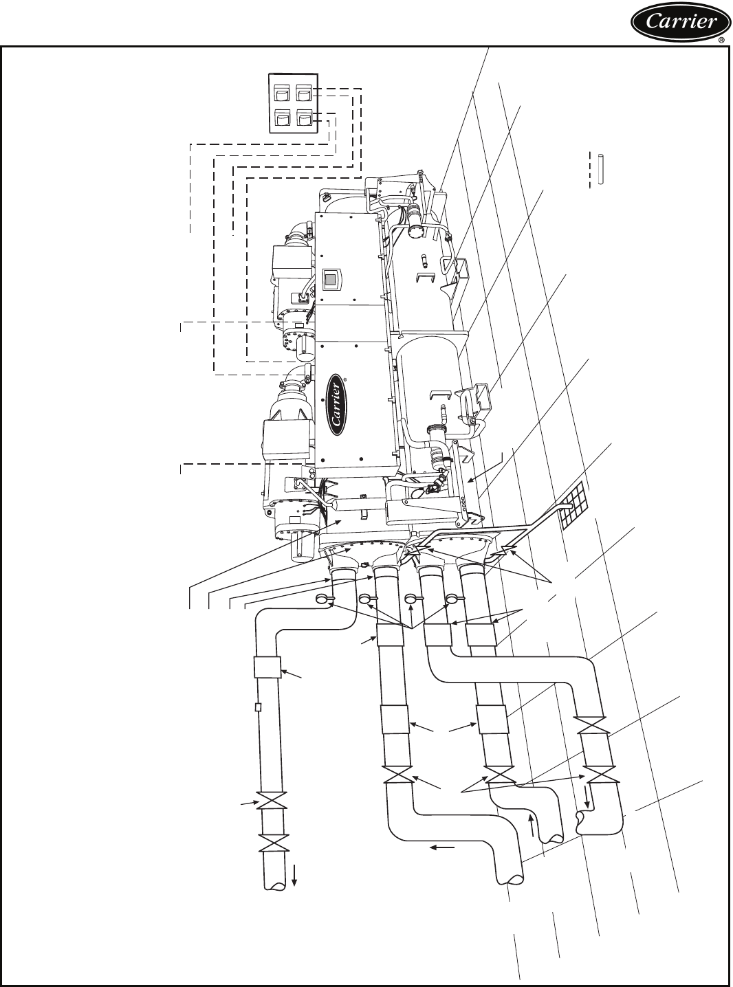
TYPICAL PIPING AND WIRING FOR 30XW EVAPORATOR AND CONDENSER
EVAPORATOR
SHUT-OFF
VALVE
BALANCING
VALVE
TO
COOLING
LOAD
FROM
COOLING
LOAD
CONDENSER
WATER
INLET
CONDENSER
WATER
OUTLET
VIBRATION
ISOLATION
VIBRATION
ISOLATION
VIBRATION
ISOLATION
PRESSURE
GAGE
SHUT-OFF
VALVE
CONDENSER
30XW
DRAIN
OUTLET
BALANCING
VALVE
SHUT-OFF
VALVE
STRAINER
INSULATE EVAPORATOR
HEADS, BOTH ENDS
VENT
INLET
CONTROL POWER
SUPPLY*
TO CHILLED
WATER PUMP
TO CONDENSER
WATER PUMP
MAIN POWER
SUPPLY
*Control power supply is not required for chillers ordered with the control power transformer option.
NOTES:
1. Wiring and piping shown are for general point-of-connection only and are not intended to show details for a
specific installation. Certified field wiring and dimensional diagrams are available upon request. The 30XW
units should be installed using certified drawings.
2. All wiring must comply with applicable codes.
3. Refer to Carrier System Design Manual for details regarding piping techniques.
4. Piping, wiring, switches, valves, vent gages, strainers, drain, and vibration isolation are all field supplied.
5. Water connections are shown on left side (discharge end) of control box in this figure. Actual connections
can be on either side according to chiller configuration ordered.
a30-4700
LEGEND
Field Wiring
Field Piping