


27
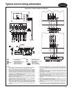
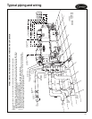
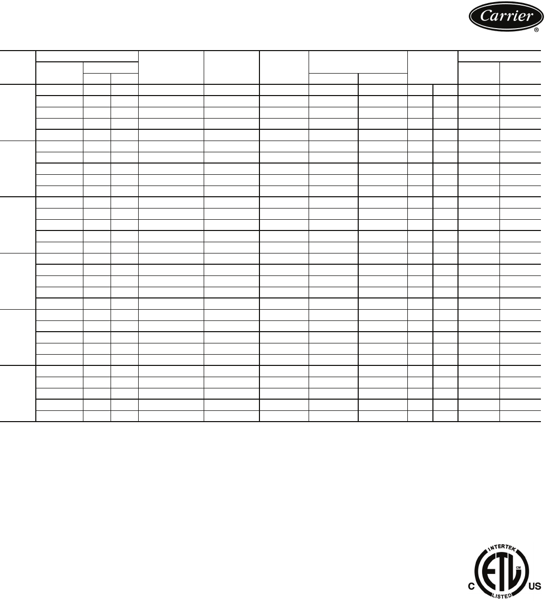
OPTIONAL DUAL INPUT POWER CONFIGURATION
LEGEND
NOTES:
1. Each main power source must be supplied from a field-supplied fused
electrical service with a (factory-installed or field-installed) disconnect
located in sight from the unit.
2. Control circuit power must be supplied from a separate source through a
field-supplied disconnect. An optional control transformer may be used
to provide control circuit power from the main unit power supply.
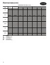
3. Maximum instantaneous current flow (ICF) during start-up is the point in
the starting sequence where the sum of the LRA for the start-up com-
pressor, plus the total RLA for all running compressors is at a maximum.
4. Maximum incoming wire size for each terminal block is 500 kcmil.
5. Maximum allowable phase imbalance is: voltage, 2%; amps, 5%.
6. Use copper conductors only.
7. The MOCP is calculated as follows:
MOCP = (2.25) (largest RLA) + the sum of the other RLAs. Size the fuse
one size down from the result. The RLAs are listed on the nameplate.
The recommended fuse size in amps (RFA) is calculated as follows:
RFA = (1.50) (largest RLA) + the sum of the other RLAs. Size the fuse
one size up from the result. The RLAs are listed on the nameplate.
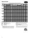
30XA
UNIT
SIZE
UNIT VOLTAGE
NO. POWER
SUPPLY
CONDUCTORS
MCA MOCP
ICF
REC FUSE
SIZE
CONTROL CIRCUIT
V-Ph-Hz
Supplied
V-Ph-Hz
MCA and
MOCP
Min Max WD XL
325
200-3-60 187 220 6/6 511.3/511.3 800/800 938/938 — 700 700 115-1-60 20
230-3-60 207 253 6/6 443.9/443.9 700/700 816/816 — 600 600 115-1-60 20
380-3-60 342 418 3/3 270.9/270.9 450/450 494/494 1537/1537 350 350 115-1-60 20
460-3-60 414 506 3/3 222.8/222.8 400/400 408/408 1270/1270 300 300 115-1-60 20
575-3-60 518 633 3/3 176.3/176.3 300/300 326/326 1016/1016 225 225 115-1-60 20
325
HM
200-3-60 187 220 6/6 649.0/649.0 1000/1000 1329/1329 — 800 800 115-1-60 20
230-3-60 207 253 6/6 565.8/565.8 1000/1000 1156/1156 — 700 700 115-1-60 20
380-3-60 342 418 3/3 341.4/341.4 600/600 700/700 2179/2179 450 450 115-1-60 20
460-3-60 414 506 3/3 283.8/283.8 500/500 578/578 1800/1800 350 350 115-1-60 20
575-3-60 518 633 3/3 226.0/226.0 400/400 462/462 1440/1440 300 300 115-1-60 20
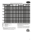
350
200-3-60 187 220 6/6 511.3/511.3 800/800 938/938 — 700 700 115-1-60 20
230-3-60 207 253 6/6 443.9/443.9 700/700 816/816 — 600 600 115-1-60 20
380-3-60 342 418 3/3 270.9/270.9 450/450 494/494 1537/1537 350 350 115-1-60 20
460-3-60 414 506 3/3 222.8/222.8 400/400 408/408 1270/1270 300 300 115-1-60 20
575-3-60 518 633 3/3 176.3/176.3 300/300 326/326 1016/1016 225 225 115-1-60 20
350
HM
200-3-60 187 220 6/6 649.0/649.0 1000/1000 1329/1329 — 800 800 115-1-60 20
230-3-60 207 253 6/6 565.8/565.8 1000/1000 1156/1156 — 700 700 115-1-60 20
380-3-60 342 418 3/3 341.4/341.4 600/600 700/700 2179/2179 450 450 115-1-60 20
460-3-60 414 506 3/3 283.8/283.8 500/500 578/578 1800/1800 350 350 115-1-60 20
575-3-60 518 633 3/3 226.0/226.0 400/400 462/462 1440/1440 300 300 115-1-60 20
400
200-3-60 187 220 6/6 578.5/578.5 1000/1000 938/938 — 700 700 115-1-60 20
230-3-60 207 253 6/6 501.6/501.6 800/800 816/816 — 700 700 115-1-60 20
380-3-60 342 418 3/3 302.9/302.9 500/500 494/494 1537/1537 400 400 115-1-60 20
460-3-60 414 506 3/3 251.6/251.6 450/450 408/408 1270/1270 350 350 115-1-60 20
575-3-60 518 633 3/3 203.5/203.5 350/350 326/326 1016/1016 250 250 115-1-60 20
400
HM
200-3-60 187 220 6/6 738.8/738.8 1200/1200 1329/1329 — 1000 1000 115-1-60 20
230-3-60 207 253 6/6 642.6/642.6 1000/1000 1156/1156 — 800 800 115-1-60 20
380-3-60 342 418 6/6 389.4/389.4 600/600 700/700 2179/2179 500 500 115-1-60 20
460-3-60 414 506 3/3 322.1/322.1 500/500 578/578 1800/1800 400 400 115-1-60 20
575-3-60 518 633 3/3 258.0/258.0 450/450 462/462 1440/1440 350 350 115-1-60 20
ICF — Maximum Instantaneous Current Flow
HM — Heat Machine Units
LRA — Locked Rotor Amps
MCA — Minimum Circuit Ampacity (for wire sizing)
MOCP — Maximum Overcurrent Protection
RLA — Rated Load Amps
WD — Wye-Delta Start
XL — Across-the-Line Start