


F O R C E D A I R O V E N M A N U A L
Cascade TEK 5245-A NE Elam Young Parkway Hilllsboro Oregon 97124
Toll Free 888-835-9250 503-648-1818 FAX 503-648-1798 info@cascadetek.com www.cascadetek.com
REV 01.08
5
Section 3
INSTALLATION
Local city, county or other ordinances may govern the use of this equipment. If you have any
questions about local requirements, please contact the appropriate local agency. Installation
may be performed by the end user. Under normal circumstances this unit is intended for use
indoors, at room temperatures between 5° and 40°C, at no greater than 80% Relative
Humidity (at 25°C) and with a supply voltage that does not vary by more than 10%.
3.1 Power Source: The electrical supply circuit to the oven must conform to all
national and local electrical codes. Consult the serial data plate for the voltage,
cycle wattage and ampere requirements before making connection. VOLTAGE
SHOULD NOT VARY MORE THAN 10% FROM THE SERIAL PLATE RATING.
This unit is intended for 50/60 Hz application. A separate circuit is recommended
to prevent possible loss of product due to overloading or failure of other
equipment on the same circuit.
3.2 Location: When selecting a site for the oven, consider all conditions which may
affect performance, such as extreme heat from steam radiators, stoves, ovens
autoclaves, etc. Avoid direct sun, fast-moving air currents, heating/cooling ducts,
and high traffic areas. To ensure air circulation around the unit allow a minimum
of 30 cm between the unit and any walls or partitions which might obstruct free
airflow.
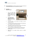
3.3 Lifting / Handling: These units are heavy and care should be taken to use
appropriate lifting devices that are sufficiently rated for these loads. Units should
only be lifted from their bottom surfaces. Doors, handles and knobs are not
adequate for lifting or stabilization. The unit should be completely restrained from
tipping during lifting or transport. All moving parts, such as shelves and trays
should be removed and doors need to be positively locked in the closed position
during transfer to prevent shifting and damage.
3.4 Leveling: The unit must sit level and solidly. Leveling feet are supplied and must
be installed in the four holes in the bottom corners of the unit. With the unit
standing upright, turn the leveling feet counterclockwise to raise level. If the unit
must be moved, turn the leveling feet in all the way to prevent damage.