


31
Installation advice
INSTALLATION
6
6
IMPORTANT
– The appliance should be installed, regulated and adapted to
function with other types of gas by a QUALIFIED INSTAL-
LATION TECHNICIAN.
Failure to comply with this condition will render the guaran-
tee invalid.
– The appliance must be installed in compliance with regula-
tions in force.
– Installation technicians must comply to current laws in force
concerning ventilation and the evacuation of exhaust gases.
– Always unplug the appliance before carrying out any main-
tenance operations or repairs.
✓
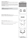
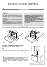
The appliance must be housed in heat-resistant units.
✓
These tops are designed to be embedded into kitchen
fixtures measuring 600 mm in depth.
✓
The walls of the units must not be higher than work top
and must be capable of resisting temperatures of 75
°C above room temperature.
✓
Do not instal the appliance near inflammable materials
(eg. curtains).
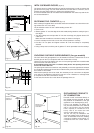
TECHNICAL INFORMATION FOR THE INSTALLER
Before installing the cooktop, remove the protective film.
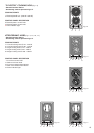
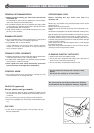
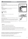
This cooktop can be built into a working surface 20 to 40 mm thick and 600 mm
deep.
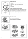
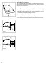
In order to install the cooker top into the kitchen fixture, a hole with the dimensions
shown in figs. 6.1a - 6.1b has to be made, keeping in consideration the following:
– within the fixture, between the bottom side of the cooker top and the upper sur-
face of any other appliance or internal shelf there must be a clearance of at least
30 mm;
– the cooker top must be kept no less than 100 mm away from any side wall;
– the cooker top must be kept at a distance of no less than 50 mm from the rear
wall.
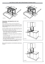
– there must be a distance of at least 650 mm between the hob and any wall cup-
board or extractor hood positioned immediately above (see fig. 6.2)
– the coatings of the walls of the unit or appliances near the cooktop must be heat
resistant ("Y" protection against heating in compliance with standards EN
60335-2-6).
Do not instal the appliance near inflammable materials (eg. curtains).
GAS COOKING HOBS
490
+
0
–
2
510
270
+ 0
– 2
288
50
30
Fig. 6.1a
490
+ 0
– 2
510
270
+ 0
– 2
288
50
30
Fig. 6.2
450 mm
650 mm
Fig. 6.1b