


38
REPAIRS
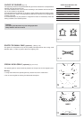
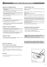
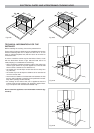
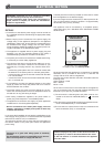
REPLACING THE POWER SUPPLY CABLE
(for 2 electrical plates and vitroceramic models)
Turn the cooktop over and unhook the terminal board cover by inserting a screwdriver
into the two hooks “A” (fig. 8.1).
Open the cable gland by unscrewing screw “F” (fig. 8.2), unscrew the terminal screws
and remove the cable.
The new supply cable, of suitable type and section, is connected to the terminal board
following the diagram fig. 8.3.
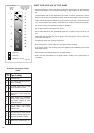
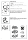
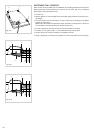
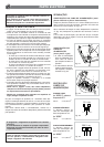
REPLACING THE POWER SUPPLY CABLE (for gas models)
-
The supply cable must be replaced with a cable of the same type.
-
The electrical cable must be connected to the terminal board following the diagrams of
fig. 8.4.
A
Fig. 8.1
F
Fig. 8.2
230 V
PE
N
L
1 (L )2
Fig. 8.3
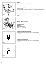
FEEDER CABLE SECTION
COOKING HOB GAS
type “H05V2V2-F”
resistance to temperatures of 90°C
230 V~ 3 x 0,75 mm
2
COOKING HOB ELECTRIC HOTPLATES
The external diameter of the supply cable must not be more than 9 mm.
tipo “H05RR-F”
230 V~ 3 x 1,50 mm
2
COOKING HOB
VITROCERAMIC
The external diameter of the supply cable must not be more than 9 mm.
type “H05RR-F”
230 V~ 3 x 1,50 mm
2
230 V
LN
Fig. 8.4