


33
TECHNICAL INFORMATION FOR THE
INSTALLER
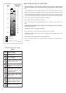
Before installing the cooktop, remove the protective film.
These cooking hobs are designed to be embedded into kitchen
fixtures measuring 600 mm in depth and from 20 to 40 mm
thick, for 2 electrical plates hob, and from 30 to 40 mm thick for
vitroceramic hob.
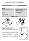
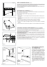
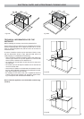
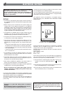
In order to install the cooker top into the kitchen fixture, a hole
with the dimensions shown in figs. 6.8a and 6.8b has to be
made, keeping in consideration the following:
– within the fixture, between the bottom side of the cooker top
and the upper surface of any other appliance or internal shelf
there must be a clearance of at least 30 mm;
– the cooker top must be kept no less than 50 mm away from
any side wall;
– the cooker top must be kept at a distance of no less than 50
mm from the rear wall.
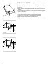
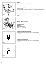
– there must be a distance of at least 650 mm between the hob
and any wall cupboard or extractor hood positioned immedi-
ately above (see figs. 6.9a and 6.9b).
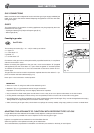
– the coatings of the walls of the unit or appliances near the
cooktop must be heat resistant ("Y" protection against heat-
ing in compliance with standards EN 60335-2-6)
.
Do not instal the appliance near inflammable materials (eg.
curtains).
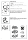
ELECTRICAL PLATES AND VITROCERAMIC COOKING HOBS
490
510
270
288
30
+ 0
– 2
+ 0
– 2
50
Fig. 6.8a
490
510
270
288
+ 0
– 2
+ 0
– 2
50
650 mm
50 mm
450 mm
Fig. 6.9b
Fig. 6.9a
650 mm
50 mm
450 mm
Fig. 6.8b