


36
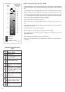
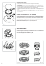
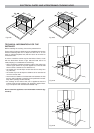
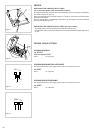
OPERATIONS TO BE PERFORMED WHEN SUBSTITUTING
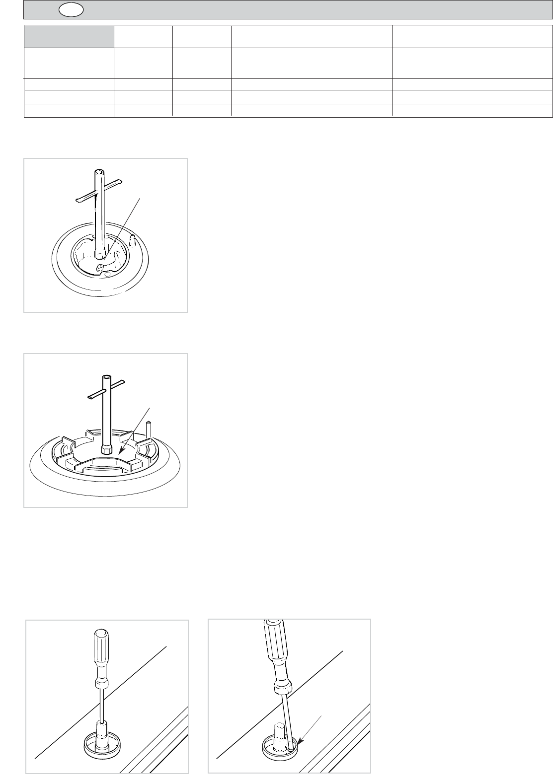
THE INJECTORS
✓ Remove the gratings, the burner covers and the knobs;
✓ Using a wrench substitute the nozzle injectors “J” (Fig. 7.3 - 7.4) with those most
suitable for the kind of gas for which it is to be used.
The burner are conceived in such a way so as not to require the regulation of the
primary air.
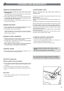
REGULATING THE BURNER MINIMUM SETTING
When switching from one type of gas to another, the minimum flow rate must also be
correct: the flame should not go out even when passing suddenly from maximum to
minimum flame.
To regulate the flame follow the instructions below:
– Light the burner
– Set the cock valve to minimum
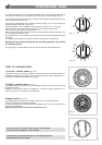
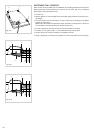
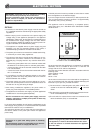
On gas valves provided with adjustment screw in the centre of the shaft (fig. 7.5):
– Using a screwdriver with max. diameter 3 mm, turn the screw inside the tap until the
correct setting is obtained.
On gas valves provided with adjustment screw on the valve body
(fig. 7.6):
–Turn the screw “A” to the correct setting with a screwdriver.
For G 30/G 31 gas, tighten the adjustment screw completely.
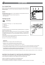
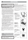
LUBRICATING THE GAS
TAPS
If one of the gas taps becomes difficult to
turn, dismantle it, thoroughly clean with
petrol and apply special high-temperatu-
re grease.
These operations must be performed by
a specialised engineer.
Fig. 7.6
A
Fig. 7.5
Fig. 7.4
J
Fig. 7.3
J
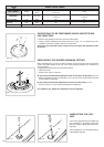
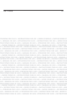
INJECTORS TABLE
Cat: II 2H3+
Semi-rapid (SR) 1,75 0,45 65 97
Rapid (R) 3,00 0,75 85 115
Triple ring (TR) 3,50 1,50 95 135
G30/G31
28-30/37 mbar
G20
20 mbar
[Hs - kW]
[Hs - kW]
Ø injector
[1/100 mm]
Ø injector
[1/100 mm]
REDUCED
POWER
NOMINAL
POWER
BURNERS
GB