


13
DVBR Series Direct Vent Gas Fireplace
20000584
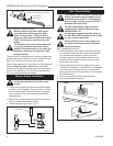
TWL100
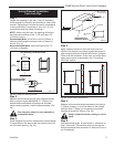
Twist Lock Pipe
3/12/99 djt
Male End
Female
End
Screw Holes
TWL100
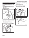
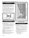
Fig. 17 Twist-Lock pipe joints.
Twist Lock Pipes
When using CFM Corporation twist-lock pipe, it is not
necessary to use silicone to seal the twist-lock joints.
The only areas that need silicone are the collars on the
fireplace, the telescoping pipe (if used) and the hori-
zontal termination connection (when necessary). The
female (flared) end secures to the fireplace first with the
male end away from the fireplace.
To join the pipes together, simply align the beads of the
male end with the grooves of the female end, twisting
the pipe until the flange on the female end touches the
external bead on the male end. Secure the joints with
three (3) sheet metal screws. (Fig. 17)
To make assembly easier, apply lubricant (vaseline or
similar) on the male end of the twist-lock pipe.
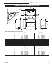
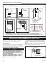
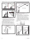
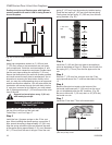
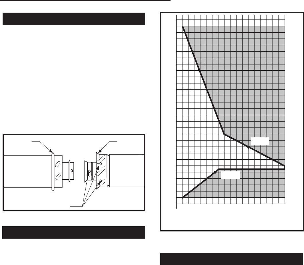
How to Use the Vent Graph
The Vent Graph should be read in conjunction with the
following vent installation instructions to determine the
relationship between the vertical and horizontal dimen-
sions to the vent system.
1. Determine the height of the center of the horizontal
vent pipe exiting through the outer wall. Using this
dimension on the Sidewall Vent Graph (Fig. 18),
locate the point intersecting with the slanted graph
line.
2. From the point of this intersection, draw a vertical
line to the bottom of the graph.
3. Select the indicated dimension, and position the
fireplace in accordance with same.
EXAMPLE A:
If the vertical dimension from the floor of the unit is 11
feet (3352 mm) the horizontal run to the face of the
outer wall must not exceed 14’ (4267 mm).
EXAMPLE B:
If the vertical dimension from the floor of the unit is 7’
(2133mm), the horizontal run to the face of the outer
wall must not exceed 8¹⁄₂’ (2590 mm).
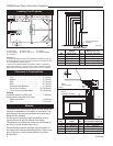
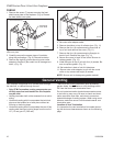
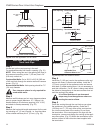
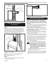
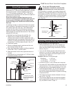
Rear Wall Vent Applications
When installed as a rear vent unit this appliance may be
vented directly to a termination located on the rear wall
behind the appliance.
• Only CFM Corporation venting components are ap-
proved to be used in these applications (See ‘Venting
Components’ listed for different installation require-
ments).
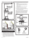
• The maximum horizontal distance between the rear
of the appliance (or end of the transition elbow in a
corner application) and the outside face of the rear
wall is 20” (508mm). (Fig. 19, 20 )
• Only one 45° elbow is allowed in these installations.
• Minimum clearances between vent pipe and com-
bustible materials are as follows:
Top - 2” (51 mm)
Sides - 1” (25 mm)
Bottom - 1” (25 mm)
Refer to Page 19 for venting
requirements for snorkels.
Vertical Dimension from the Floor of the Unit
to the Center of the Horizontal Vent Pipe
Fig. 18 Sidewall venting graph. (Dimensions in feet.)
DV Graph
3
4
5
6
7
8
9
10
11
12
13
14
15
16
17
18
19
20
21
22
23
24
25
26
27
28
29
30
3
4 5 6 7 8 9 10 11 12 13 14 15 16 17 18 19 20
eg: A
eg: B
Horizontal Dimension from the Outside Face of the
Wall to the Center of the Fireplace Vent Flange