


8
DVBR Series Direct Vent Gas Fireplace
20000584
Always check for gas leaks with a mild
soap and water solution applied with a
brush no larger than 1” (25 mm). Never
apply soap and water solution with a spray
bottle. Do not use an open flame for leak
testing.
The fireplace valve must not be subjected
to any test pressures exceeding 1/2 psi.
Isolate or disconnect this or any other gas
appliance control from the gas line when
pressure testing.
The gas control is equipped with a captured screw type
pressure test point, therefore it is not necessary to pro-
vide a 1/8” test point up stream of the control.
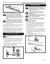
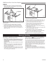
When using copper or flex connector use only approved
fittings. Always provide a union when using black
iron pipe so the gas line can be easily disconnected for
burner or fan servicing. (Fig. 6) See the gas specifica-
tions for pressure details and ratings.
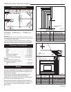
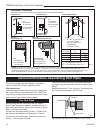
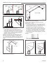
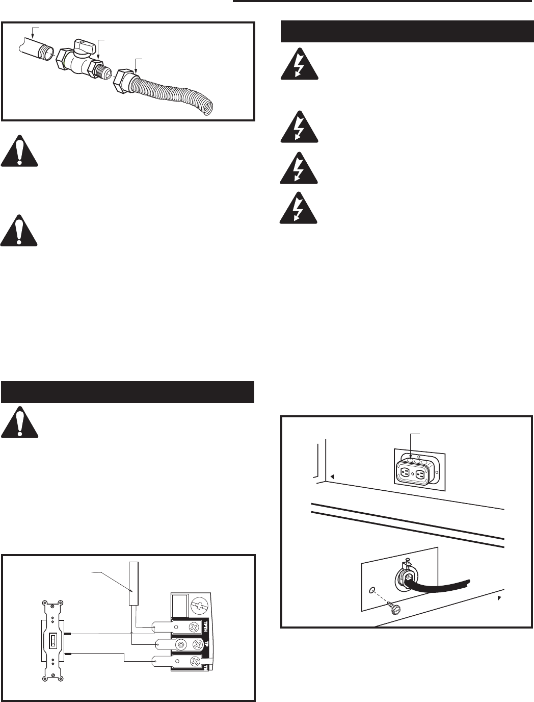
Fig. 9 EB-1 receptacle.
FP580
FP580
INSTA VENT FREE
EB1 JUNCTION BOX
11/18/97
OUTSIDE
ELECTRICAL BOX
INSIDE
FRONT OF UNIT
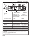
Remote Switch Installation
Do not wire the remote ON/OFF wall switch
for this gas appliance into a 120v power
supply.
1. Thread wire through the electrical knockout located
on either side of fireplace. Do not cut wire or insula
-
tion on metal edges. Ensure that wire is protected.
Run the other end to a conveniently located wall
receptacle box.
2. Attach wire to switch and install switch into recepta-
cle box. Attach cover plate to switch.
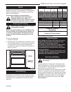
3. Connect wiring to gas valve. (Fig. 7)
W584-9
WIRING DIAGRAM
1/8/99 djt
11/9/99 added thermopile
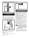
Thermopile
Fig. 7 Remote switch wiring diagram for R models.
W584-9
Switch
Gas Valve
EB-1 Electrical Box
The fireplace, when installed, must be elec-
trically connected and grounded in accor-
dance with local codes or, in the absence
of local codes, with the current CSA C22.1
Canadian Electrical Code.
For USA installations, follow the local
codes and the national Electrical Code
ANSI/NFPA No. 70.
It is strongly suggested that the wiring of
the EB-1 Electrical Junction Box be carried
out by a licensed electrician.
Ensure that the power to the supply line
has been disconnected before commenc-
ing this procedure.
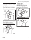
EB1 (Receptacle) Hook-Up
1. Remove contents from plastic bag. Remove knock-
out in center of electrical box. Remove coverplate
from fireplace and knockout. Insert connector
through coverplate, plate and box. Screw nut on
connector with screws provided (2) to secure the
coverplate to the plate.
2. Connect black positive wire to brass screw (polar
-
ized side) of receptacle. The white wire is connected
to chrome screw. The ground wire is connected to
green ground screw of the receptacle. Fit receptacle
into electrical box.
3. Screw cover plate provided to electrical box.
4. Secure receptacle to fireplace.
FP297A
INSTA VENT FREE
UVHB26 GAS SUPPLY
7/1/98
FP297A
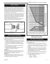
Fig. 6 Typical gas supply installation.
1/2” Gas Supply
1/2” NPT X 1/2” Flare Shut-off Valve
3/8” Flex line
(from valve)