


20
DVBR Series Direct Vent Gas Fireplace
20000584
1
2
3
4
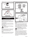
1
2
3
4
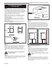
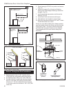
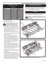
1 + 2 + 3 + 4 = 270°
FP1179
Fig. 42 Maximum elbow usage.
FP1184
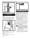
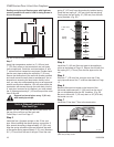
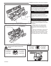
Typical roof/ceiling
support apps.
FP1184
Typical Roof
Support Ap-
plication
Typical Ceiling Sup
-
port Application
Fig. 44 Venting supports.
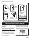
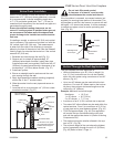
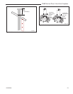
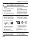
Joist
Attic Insulation Shield
Ceiling
Installation
Upper Floor
11”
Firestop
Spacer
Nails (4)
Fig. 43 Place firestop spacer(s) and secure.
VR404
11”
5. Place firestop(s) #7DVFS into position and secure.
(Fig. 43)
6. Install roof support (Fig. 44) and roof flashing
making sure upper flange of flashing is below the
shingles. (Fig. 46)
7. Install appropriate pipe sections until above the
flashing. (Fig. 46)
8. Install storm collar and seal around the pipe.
9. Add additional vent lengths for proper height.
10. Apply high temperature sealant to 4” and 7” collars
of vent termination and install.
If there is a room above ceiling level, firestop spacers
must be installed on both the bottom and the top side
of the ceiling joists. If an attic is above ceiling level
a 7DVAIS (Attic Insulation Shield) must be installed.
The enlarged ends of the vent section always face
downward.
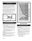
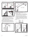
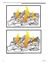
Vertical Through-the-Roof Installation
Max. Height 40’ (12.2m)
Min. Height 8’ (2.4m)
Max. 10’ (3m)
FP1183
Max. Height
40’ (12.2m)
Min. Height 8’
(2.4m)
Max. 10’ (3m)
Fig. 41 Support straps for horizontal runs.
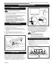
1. Locate your fireplace.
2. Plumb to center of the (4”) 90° transition elbow
(7DVRT90) from ceiling above and mark position.
3. Cut opening equal to 9³⁄₈" x 9³⁄₈" (240 x 240 mm).
4. Proceed to plumb for additional openings through
the roof. In all cases, the opening must provide a
minimum of 1” (25 mm) clearance to the vent pipe,
i.e., the hole must be a minimum of 9³⁄₈" x 9³⁄₈" (240
x 240 mm).