


30
DVBR Series Direct Vent Gas Fireplace
20000584
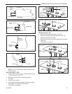
4. For conver-
sion to Natural
Gas remove the
manifold mounting
bracket. Replace
the nut and screw
removed earlier.
Attach the air shut-
ter to the burner
tube and secure with screw. Tighten screw. For con-
version to LP Gas, remove the air shutter retaining
screw and remove air shutter. Remove the hex nut
and screw as shown in Figure 65. Slide the manifold
mounting bracket onto the manifold where the split
nut was removed. Slide the split nut on and install
the orifice. Tighten the orifice. (Fig. 66) Assemble the
manifold mounting bracket to the burner where the
nut and screw were removed. Tighten the nut and
screw.
5. For conversion to natural gas re-install manifold
to burner pan with 3/4” wrench and tighten until
secure.
Fuel Conversion Instructions
To convert the DVBR unit from one gas type to another
follow these instructions:
1. Remove control cover to gain access to valve.
Remove glass door. (See “Glass Frame Removal”,
Page 23, Fig. 48)
2. Remove logs if previously installed.
Valve Conversion - Honeywell Valve
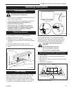
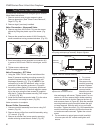
3. Remove cap from HI/LO knob. This can be accom-
plished by lifting the plastic cap off the screw. (Fig.
59)
4. Remove the screw from center of HI/LO knob with
small screwdriver turning counterclockwise. (Fig. 59)
CO101
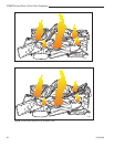
Gas Conversion
Manifold
2/12/99 djt
Manifold
Assembly
Orifice
Log Support
Pilot
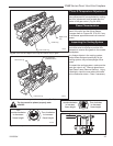
Fig. 61 Remove manifold assembly.
CO101
Burner Pan
5. Insert conversion screw (supplied in conversion kit)
in center of HI/LO knob. Blue for natural gas, red for
LP.
6. Tighten screw, replace cap.
Valve conversion is complete.
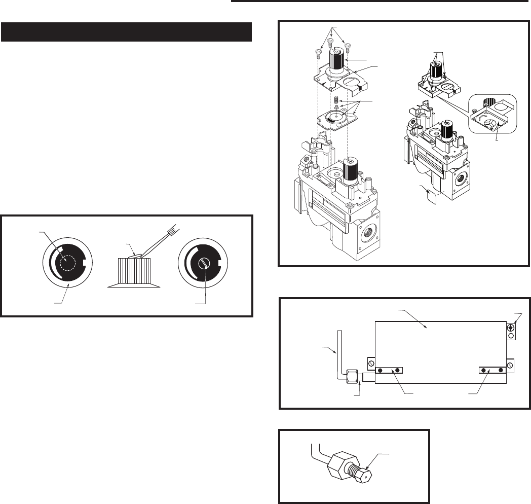
Valve Conversion - SIT Valve
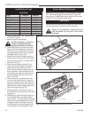
1. Using the TORX T20 bit, remove and discard the
three (3) pressure regulator mounting screws (A),
pressure regulator tower (B) and the spring and
diaphragm assembly (C(). (Fig. 60) NOTE: If the
conversion is for the 822 electronic valve, cut the
metal tab off the regulator as shown in Figure 60.
2. Insure the rubber gasket (D) is properly positioned
and install the new HI/LO pressure regulator assem-
bly to the valve using the new screws (E) supplied
with the kit. Tighten the screws securely. (Ref. torque
= 25 in/lb) (Fig. 60)
3. Install the enclosed conversion label (F) to the valve
body where it can easily be seen. (Fig. 60)
Valve conversion is complete.
Burner Orifice Conversion
1. Unscrew manifold assembly from burner using 3/4”
wrench. (Fig. 61)
2. Remove burner orifice from manifold assembly using
1/2” wrench. (Fig. 62)
3. Remove air shutter from burner pan by removing
shutter retaining screw then air shutter. (Fig. 63)
CO100
Gas conversion
HI-LO knob
3/15/99 djt
L
O
H
I
L
O
H
I
Hi-Lo Knob
Cap
Lift Open
Fig. 59 Remove center screw from Hi-Lo knob.
Remove
Center Screw
CO100
CO102
Gas Conversion
2/15/99 djt
CO102
Burner
Orifice
Fig. 62 Remove burner orifice,
replace with conversion orifice.
FC107
SIT820
valve conversion
10/03
A
B
C
O
F
F
P
I
L
O
T
O
D
E
F
FC108
SIT
regulator
conversion
10/03
O
F
F
P
I
L
O
T
O
Fig. 60 Remove mounting screws, pressure regulator tower
and spring and diaphragm assembly. Replace regulator.
FC107/108
Cut here
for 822
Valve