


14
DVBR Series Direct Vent Gas Fireplace
20000584
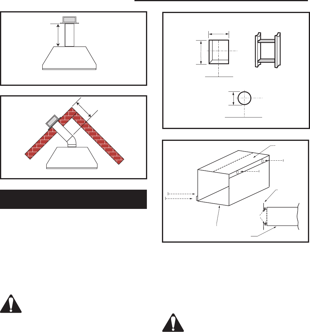
Rear Wall Vent Installations -
Twist Lock Pipe
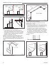
Step 1
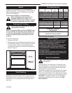
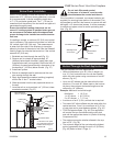
Locate and cut the vent opening in the wall.
For combustible walls first frame in opening. (Fig. 21)
NOTE: When using flex vent, the opening will have to
be measured according to the 1” (25 mm) rise in 24”
(610 mm) vertical run.
Combustible Walls:
Cut a 10³⁄₈”H x 9³⁄₈” W (265 mm
x 240 mm) hole through the exterior wall and frame as
shown. (Fig. 21)
Noncombustible Walls:
Hole opening should be 7¹⁄₂”
(191 mm) diameter.
Zero clearance sleeve is only required for
combustible walls.
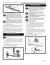
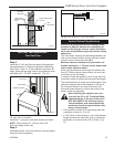
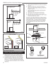
Step 2
Measure wall thickness and cut zero clearance sleeve
parts to proper length (Maximum 12” / 305mm). As-
semble sleeve to its maximum opening (10³⁄₈” x 9³₈”)
and attach to firestop assembly. (Fig. 22)
Step 3
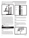
Measure the horizontal length requirement for the vent-
ing including a 2” (51 mm) overlap, i.e. from the elbow
to the outside wall face plus 2” (51 mm). (Fig. 20)
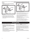
Step 4
Install the 4” (102 mm) vent to the appliance collar and
secure with three (3) sheet metal screws. Install the 7”
(175 mm) vent pipe to the appliance collar and secure
with three (3) sheet metal screws. It is not necessary to
seal this connection. If a 45° elbow is being used attach
the elbow to the appliance in the same manner then at-
tach the venting to the elbow.
It is critical that there is no downward
slope away from the appliance when con-
necting the vent or elbow.
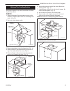
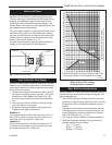
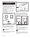
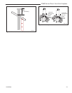
Step 5
Guide the venting through the vent hole as you place
the appliance in its installed position. Guide the 4”
(102 mm) and 7” (175 mm) collar of the vent termina-
tion into the outer ends of the venting. Do not force
the termination. If the vent pipes do not align with the
termination, remove and realign the venting at the appli-
ance flue collars. (Fig. 23) Attach the termination to the
wall as outlined in the instruction sheet supplied with
the termination.
VO584-100
Vent Opening
2/99 djt
Fig. 21 Locate vent opening on wall.
Framing
Detail
9³⁄₈"
(240 mm)
10³⁄₈"
(265 mm)
Fireplace Hearth
7¹⁄₂" Dia.
(191 mm)
Vent Opening - Noncombustible Wall
Fireplace Hearth
VO584-100
Vent Opening - Combustible Wall
CFM135
Zero Clearance Sleeve
2/26/01 sta
#8 Screws
(2)
Adjustable Zero
Clearance Sleeve
Firestop
#8 Screws (2)
#8 Screws (2)
Max. Length
12” (294 mm)
Fig. 22 Adjustable zero clearance sleeve.
CFM135a
FP1188
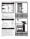
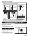
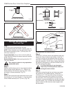
Fig. 19 Rear vent application, no elbows.
20” (506 mm)
Max.
Top View Flat Installation
Fig. 20 Rear vent application, one 45° elbow.
Top View Corner Installation
FP1188
20” (506 mm)
Max.