


35
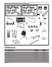
DVBR Series Direct Vent Gas Fireplace
20000584
Optional Accessories
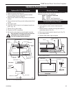
Optional Fk-12 Fan Hook-up
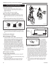
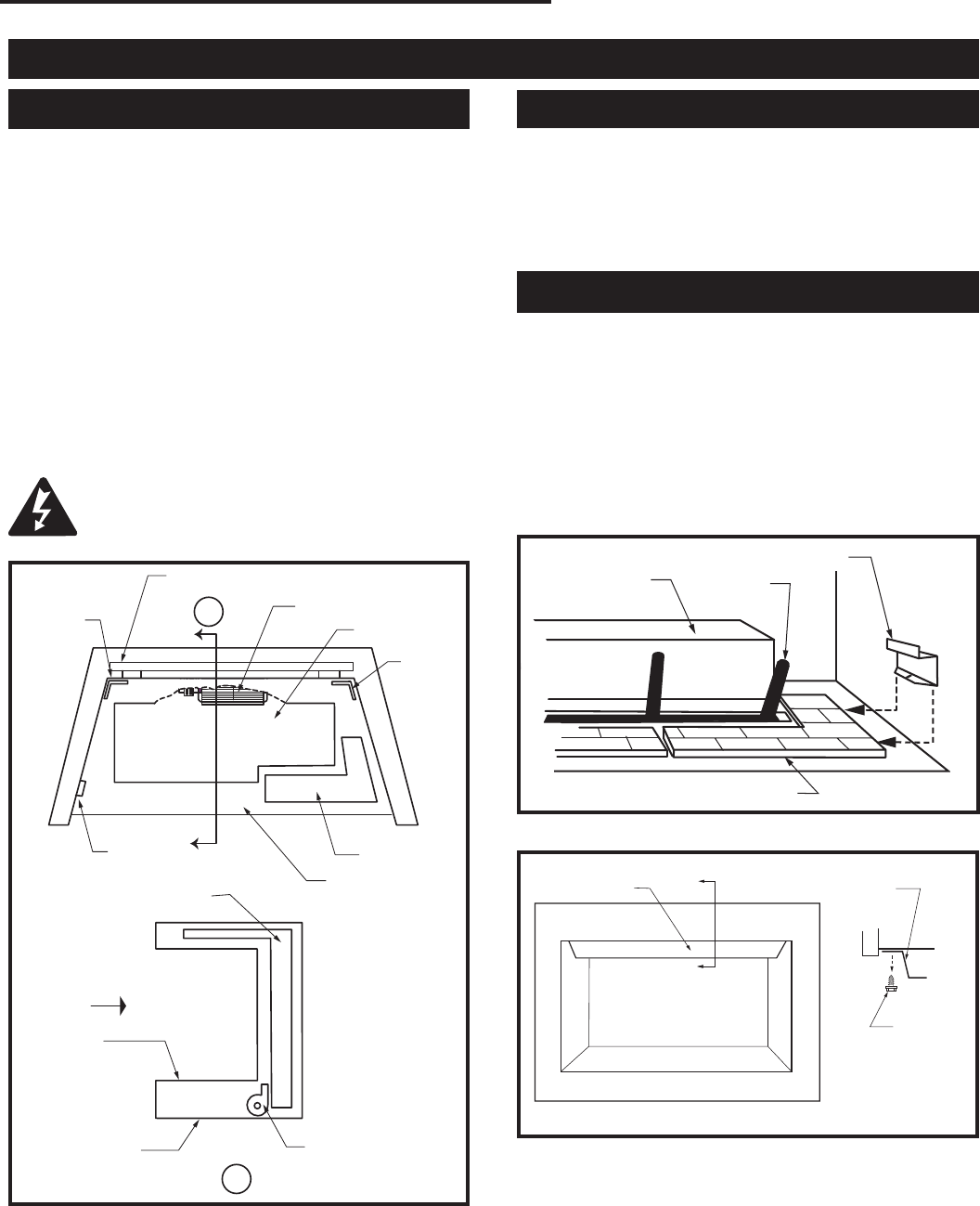
1. Remove control cover from unit.
2. Remove glass door by rotating latches at bottom
corners of door. Refer to Page 23.
3. Remove the 9 screws securing burner to combustion
bottom.
4. Remove burner by lifting up and rotating toward front
of unit.
5. Set burner aside.
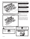
6. Install FK-12 fan in back of unit between hearth sup
-
ports. (Fig. 72)
7. Secure fan on velcro strips.
8. Plug fan into EB-1 receptacle.
9. Be sure fan motor does not touch hearth supports.
Any electrical re-wiring of this fan must be
completed by a qualified electrician.
Turn off all power before hook-up.
A
A
584-10
Fan placement
DVBR Series
3/11/99 djt
Front of
Unit
Cold Air Box
Cold Air Box
Base Pan
Base Pan
Hearth Pan
Hearth Pan
Hearth
Support
Hearth
Support
See
Detail
Detail
FK-12 Fan
FK-12 Fan
Access Cover
EB-1 Re-
ceptacle
Fig. 72 FK-12 Fan Kit placement.
584-10
Top View
Side View
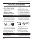
Remote Controls
Optional remote control units are available to control
different functions of the appliance.
Model Functions Controlled
RC1 ON/OFF
RC2 ON/OFF and Temperature
IMTFK Wall mounted thermostat control
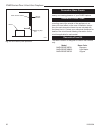
Ceramic Refractory Panels
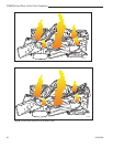
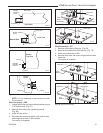
1. Remove glass and logs.
2. Insert supports under ceramic hearth panels.
(Fig. 73)
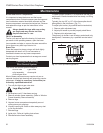
3. Remove three (3) screws securing heat shield to
combustion dome. (Fig. 74)
4. Place rear ceramic panel in back of unit. (Fig. 75)
5. Place side panels.
6. Replace heat shield, logs and glass.
H101
Ceramic Panel Supports
3/16/99 djt
Burner
Hearth Panel
Ceramic Support
Fig. 73 Ceramic support.
H101
Grate
H103
heat shield
3/1/99 djt
(3) Screws
Heat Shield
Front View
Fig. 74 Heat shield.
H103
Section A
Heat Shield
Side View
Section A