


20012301
11
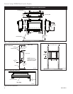
Vermont Castings DVR28 Direct Vent Gas Fireplace
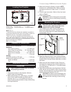
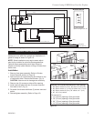
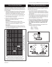
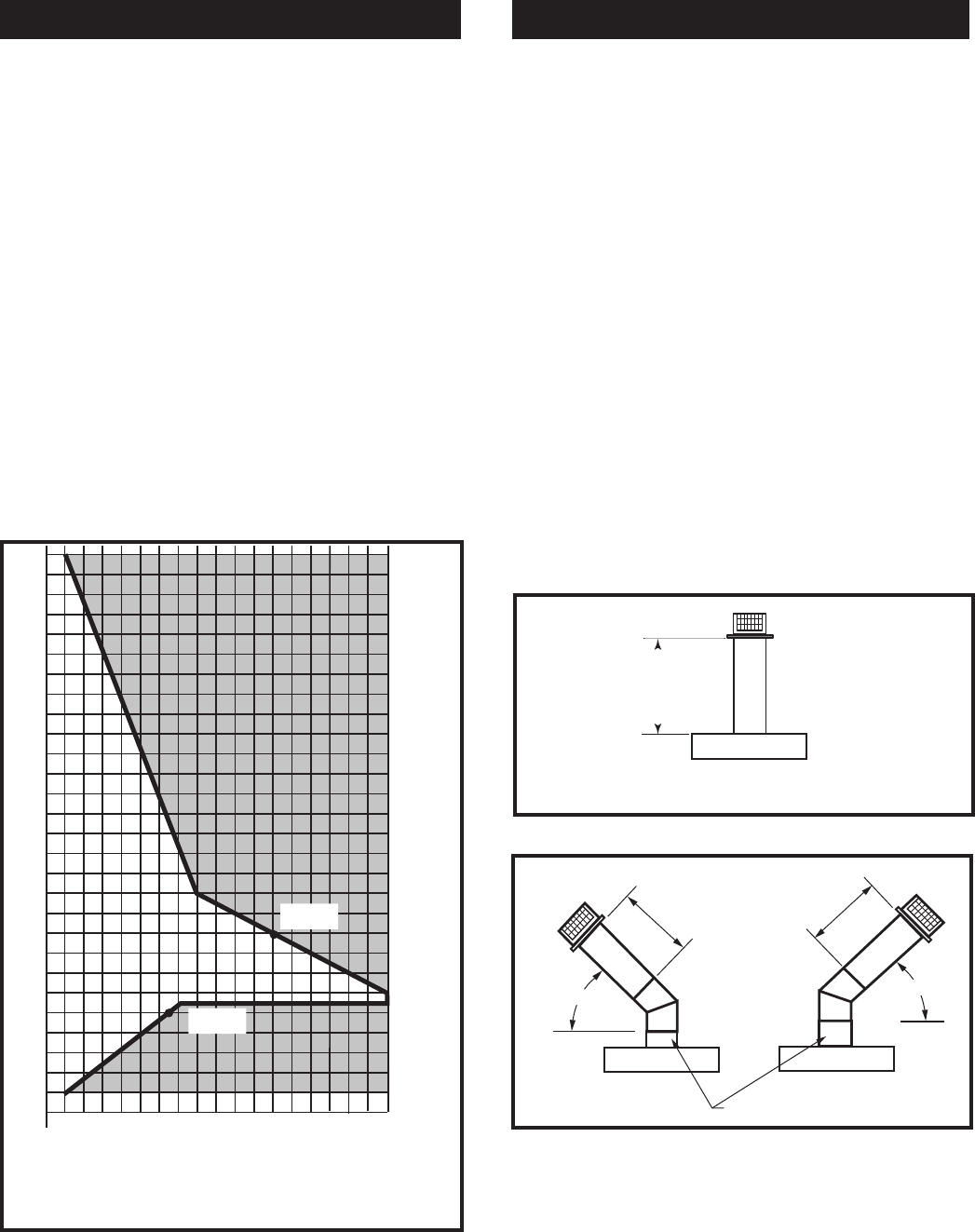
The vent chart should be read in conjunction with the
following vent installation instructions to determine the
relationship of the vertical and horizontal dimensions of
the vent system.
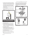
1. Determine the height of the center of the horizontal
vent pipe exiting through the outer wall. Using this
dimension on the Sidewall Vent Graph (Fig. 14)
locate the point intersecting with slanted graph line.
2. From the point of this intersection, draw a vertical
line to the bottom of the graph.
3. Select the indicated dimension, and position the
fireplace in accordance with same.
Example A:
If the vertical dimension from the floor of the
fireplace is 11’ (3.4 m) the horizontal run to the face
of the outer wall must not exceed 14’ (4.3 m).
Example B:
If the vertical dimension from the floor of the unit is
7’ (2.14 m), the horizontal run to the face of the outer
wall must not exceed 8¹⁄₂’ (2.6 m).
How to Use the Vent Graph
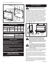
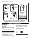
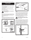
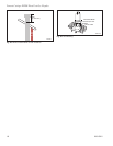
Rear Wall Venting Applications
When installed as a rear vent unit this appliance may
be vented directly to a termination located on the rear
wall behind the appliance.
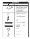
• Only CFM Corporation venting components are
approved to be used in these applications. (Refer to
“Venting Components” listed for different installation
requirements)
• The maximum horizontal distance between the rear
of the appliance (or end of the transition elbow in a
corner application) and the outside face of the rear
wall is 20” (508 mm). (Fig. 15 & 16)
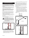
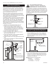
• Only one 45° elbow is allowed in these installations.
• If using a 45° elbow at fireplace, you must start
out using an 8” (203 mm) or 12” (305 mm) sec-
tion of pipe first attached to heater then a 45°
elbow.
• Minimum clearances between vent pipe and com-
bustible materials are as follows:
Top - 2” (51 mm)
Sides - 1” (25 mm)
Bottom - 1” (25 mm)
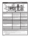
Horizontal dimension from the outside face of the
wall to the center of the fireplace vent flange
Sidewall vent graph showing the relationship between vertical
and horizontal dimensions for a Direct Vent flue system.
Vertical dimension from the floor of the unit
to the center of the horizontal vent pipe
3
4
5
6
7
8
9
10
11
12
13
14
15
16
17
18
19
20
21
22
23
24
25
26
27
28
29
30
eg: A
eg: B
Fig. 14 Sidewall venting graph. (Dimensions in feet)
FP1780
rear vent no elbows
3/07
Rear Vent Top View
FP1780
Fig. 15 Rear vent application, no elbows.
20”
(508 mm)
Max.
FP1779
Fig. 16 Rear vent application, one 45° elbow.
FP1779
Rear Vent-Top View
3/07
20”
(508 mm)
Max.
45°
45°
20”
(508 mm)
Max.
Start with 8” (203 mm) or 12”
(305 mm) Pipe Section