


20012301
13
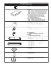
Vermont Castings DVR28 Direct Vent Gas Fireplace
Vertical Sidewall Applications
Since it is very important for the venting system
to maintain balance between the combustion air
intake and the flue gas exhaust, certain limitations
as to vent configurations apply and must be strictly
adhered to.
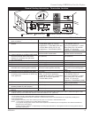
The Vent Graph shows the relationship between vertical
and horizontal side wall venting and will help to deter-
mine the various dimensions allowable.
Minimum clearance between vent pipes and com-
bustible materials is 2”(51 mm) on top and 1” (25
mm) on the bottom and sides unless otherwise
noted.
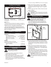
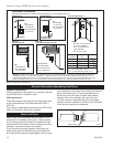
When vent termination exits through foundations less
than 20” below siding outcrop, the vent pipe must
flush up with the siding. It is always best to locate the
fireplace in such a way that minimizes the number of
offsets and horizontal vent length.
The horizontal vent run refers to the total length of vent
pipe from the flue collar of the fireplace to the face of
the outer wall.
Horizontal plane means no vertical rise exists on this
portion of the vent assembly.
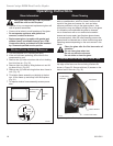
When installing the appliance as a rear
vent unit, the 90° or 45° transition elbow
is NOT INCLUDED in the following criteria
and calculations, and unless specifically
mentioned should be ignored when calcu-
lating venting layouts.
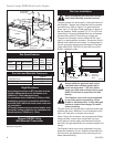
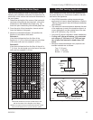
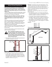
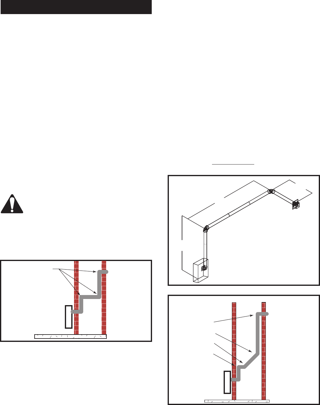
• The maximum number of 90° elbows per side wall
installation is three (3). (Fig. 20)
FP1755
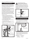
Horizontal Run
2/07
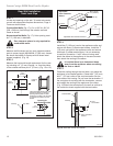
A 10’
(254 cm)
B 7’
(178 cm)
8’
(244 cm)
A + B = 17’
(518 cm) Max.
FP1755
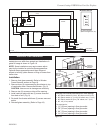
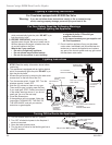
Fig. 21 Maximum vent run with elbows.
Fig. 20 Maximum three (3) 90° elbows per installation.
3 x 90°
Elbows
FP1754
Example: According to the vent graph (Page 11) the
maximum horizontal vent length in a system with a 7.5’
(2.3 m) vertical rise is 20’ (6 m) and if a 90° elbow is
required in the horizontal vent it must be reduced to 17’
(5.2 m). In Figure 21 Dimension A plus B must not be
greater than 17’ (5.2 m).
In Figure 21, dimension A plus B must not be greater
than 17’ (5.2 m).
• The maximum number of 45° elbows permitted per
side wall installation is two (2). These elbows can be
installed in either the vertical or horizontal run.
• For each 45° elbow installed in the horizontal run,
the length of the horizontal run MUST be reduced by
18” (45 cm). This does not apply if the 45° elbows
are installed on the vertical part of the vent system.
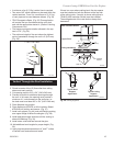
• The maximum number of elbow degrees in a system
is 270°. (Fig. 22)
Example:
Elbow 1 = 90°
Elbow 2 = 45°
Elbow 3 = 45°
Elbow 4 = 90°
Total angular variation = 270°
• If a 90° elbow is used in the horizontal vent run
(level height maintained) the maximum horizontal
vent length is reduced by 36” (914 mm). This does
not apply if the 90° elbows are used to increase or
redirect a vertical rise. (Fig. 21)
1
2
3
4
1 + 2 + 3 + 4 = 270°
FP1756
Fig. 22 Maximum elbow usage.