


12
20012301
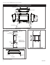
Vermont Castings DVR28 Direct Vent Gas Fireplace
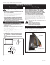
STEP 1
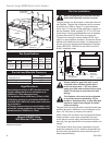
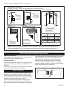
Locate vent opening on the wall. To locate hole center
consult with appropriate fireplace dimensions, Page 4.
Frame as shown below.
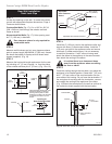
Combustible Walls (Fig. 17): Cut a 10³⁄₈”H x 9³⁄₈” W
(264 x 240 mm) hole through the exterior wall and
frame as shown.
Noncombustible Walls (Fig. 17): Hole opening must
be 7¹⁄₂” (190 mm) in diameter.
Zero clearance sleeve is only required for
combustible walls.
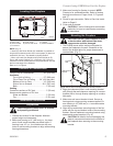
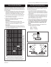
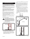
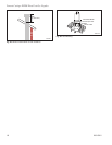
STEP 2
Measure wall thickness and cut zero clearance sleeve
parts to proper length (MAXIMUM 12”/305 mm). Assem-
ble sleeve and attach to firestop with #8 sheet metal
screws (supplied). (Fig. 18)
STEP 3
Measure the horizontal length requirement for the vent-
ing including a 2” (51 mm) overlap, i.e. from the elbow
to the outside wall face plus 2” (51 mm). (Fig. 15 or 16)
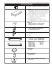
FP1752
Zero Clearance Sleeve
2/07
Max. Length
12” (305mm)
#8 Screws (2)
#8 Screws
(2)
Adjustable
Zero Clearance
Sleeve
#8 Screws
(2)
Adjustable Zero Clearance Sleeve
ZCS101
Fig. 18 Adjustable zero clearance sleeve.
Firestop
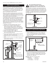
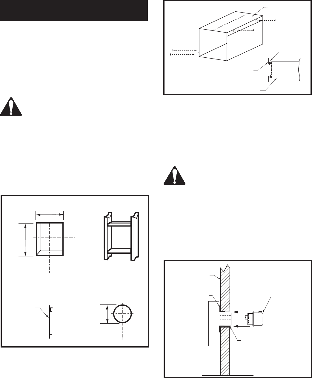
STEP 4
Install the 4” (102 mm) vent to the appliance collar and
secure with three (3) sheet metal screws. Install the 7”
(178 mm) vent pipe to the appliance collar and secure
with three (3) sheet metal screws. It is not necessary
to seal this connection. If a 45° elbow is being used,
attach the elbow to the appliance in the same manner
then attach the venting to the elbow.
It is critical there is no downward slope
away from the appliance when connecting
the vent or elbow.
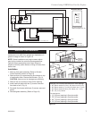
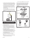
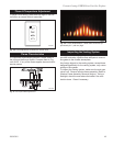
STEP 5
Guide the venting through the vent hole a you place the
appliance in its installed position. Guide the 4” (102 mm)
and 7” (178 mm) collar of the vent termination into the
outer ends of the venting. Do not force the termination. If
the vent pipes do not align with the termination, remove
and reali
gn the venting at the appliance flue collars.
(Fig. 19) Attach the termination to the wall as outlined in
the instruction sheet supplied with the termination.
FP1751
vent opening
2/07
Vent Opening for Combustible Wall
9³⁄₈”
(240mm)
10³⁄₈”
(264mm)
Fireplace Hearth
Framing
Detail
Opening for
Noncombustible Wall
7¹⁄₂”
(190 mm)
FP1751
Fig. 17 Locate vent opening on wall.
Firestop
Top Tabs
Bottom Tabs
Install provided firestop with zero
clearance sleeve into framing
opening after drywall or finish
material is installed. Use the tabs
for clearance locators top and
bottom.
FP1005
Side View Vent Termination
1/25/00 djt
Finished Wall
Vent
Termination
FP1753
Fig. 19 Side view of final unit location.
Firestop
Zero Clearance
Sleeve
Rear Wall Installation
Twist Lock Pipe