


6
20012301
Vermont Castings DVR28 Direct Vent Gas Fireplace
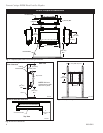
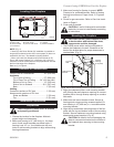
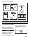
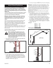
Sheet Metal
Screws (8)
Sheet Metal
Screws (4)
FP1785
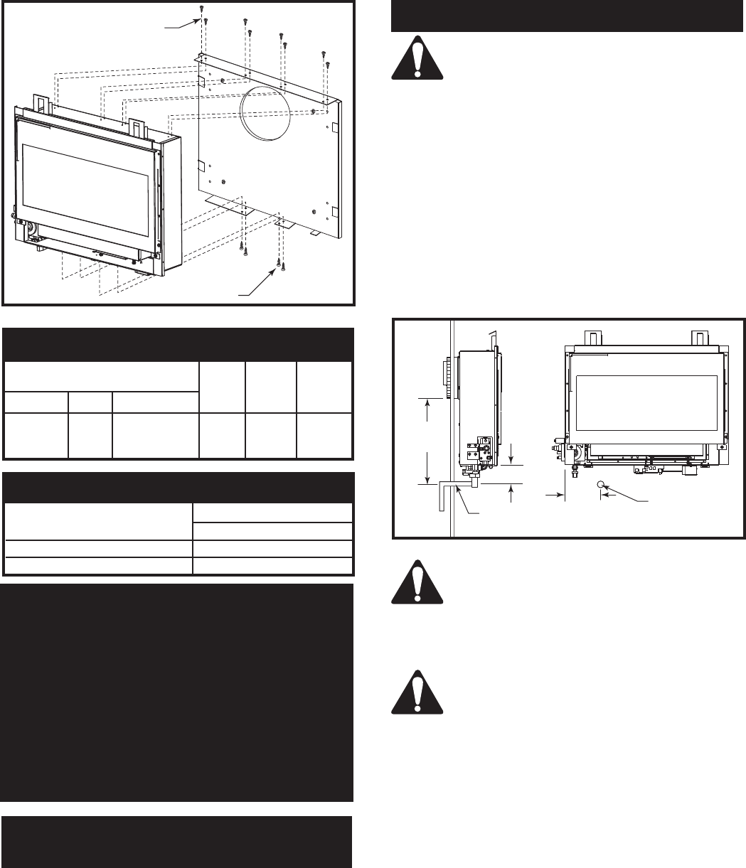
Wall Mounting Bracket
Secured to Walll
DVR28
Fig. 6 Secure fireplace to wall mounting bracket.
High Elevations
Input ratings are shown in BTU per hour and are
certified without deration for elevations up to
4,500 feet (1,370m) above sea level.
For elevations above 4,500 feet (1,370m) in USA,
installations must be in accordance with the cur-
rent ANSI Z223.1/NFPA 54 and/or local codes hav-
ing jurisdiction.
In Canada, please consult provincial and/or local
authorities having jurisdiction for installations at
elevations above 4,500 feet (1,370m).
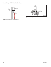
Gas Line Installation
When purging the gas lines, the front win-
dow frame assembly must be removed.
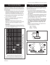
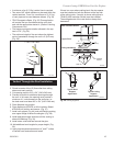
The gas pipeline can be brought in under the bottom of
the fireplace. The gas line connections will be covered
by bottom trim. Refer to Figure 7 for gas line dimen-
sions. Use 1/2” rigid pipe. When gas line is in place un-
der the fireplace, install supplied 1/2” FPT to 3/8” flare
brass fitting. Connect preinstalled flex line on fireplace
to brass fitting with 3/8” flare fitting on supply line.
The gas line connection can be made with 3/8” rigid
pipe or an approved flex connector. Since some munici-
palities have additional local codes, it is always best to
consult your local authority and the National Fuel Gas
Code, ANSI Z223.1/NFPA 54 in the USA or the CSA-
B149.1 installation code.
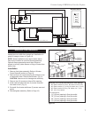
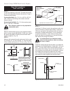
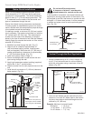
Remote ON/OFF Hi/Lo
Wall Mounted Transmitter
The DVR28 is equipped with a wireless transmitter. No
wires are required.
Always check for gas leaks with a mild
soap and water solution applied with a
brush no larger than 1” (25 mm). Never
apply soap and water solution with a spray
bottle. Do not use an open flame for leak
testing.
The fireplace valve must not be subjected
to any test pressures exceeding 1/2 psi.
Isolate or disconnect this or any other gas
appliance control form the gas line when
pressure testing.
The gas control is equipped with a captured screw type
pressure test point, therefore it is not necessary to pro-
vide a 1/8” test point up stream of the control.
When using a flex connector use only approved fittings.
Always provide a union when using black iron pipe
so the gas line can be easily disconnected for burner
servicing. See gas specification for pressure details and
ratings.
The fireplace valve must not be subjected to any test
pressures exceeding 1/2 psi. Isolate or disconnect this
and any other gas appliance control from the gas line
when pressure testing.
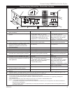
Inlet Minimum 5.5” w.c.
Inlet Maximum 14.0” w.c.
Manifold Pressure 3.5” w.c.
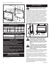
Gas Inlet and Manifold Pressures
Natural
12”
(318 mm)
6”
(152 mm)
FP1787
gas line install
3/07
1”
(32 mm)
Gas Line
Through Wall
Gas Line
Opening in
Wall
FP1787
Fig. 7 Recommended gas line installation.
Max. Min. Air
Input Input Shutter
Model Fuel Gas Control BTU/h BTU/h Setting
1/8”
DVR28IN Nat. Millivolt Hi/Lo 18,500 16,500 open
on sides
Gas Specifications