


20012301
5
Vermont Castings DVR28 Direct Vent Gas Fireplace
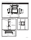
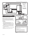
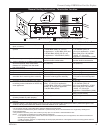
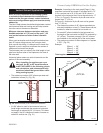
A) Flat on wall B) Cross corner C) **Island
D) *Room divider E) *Flat on wall corner F) Chase installation
Y) 6” minimum
NOTE: (Fig. 4)
** Island (C) and Room Divider (D) installation is possible as
long as the horizontal portion of the vent system (X) does not
exceed 20’ (610 cm). See details in Venting Section.
* When you install your fireplace in(D) Room divider or (E)
Flat on wall corner positions (Y), a minimum of 6” (153 mm)
clearance must be maintained from the perpendicular wall and
the front side edge of the fireplace.
Refer to (Y) in Figure 4.
Locating Your Fireplace
Y
E
A
B
C
D
F
Y
B
X
LU584-1
Locating unit
2/4/99 djt
LU584-R
Fig. 4 Locate gas fireplace.
Front of Unit to Combustibles ...................36” (914 mm)
Appliance
Top of Unit to Ceiling ..........................27” (686 mm)
Top of Face Trim to Ceiling ........24” (610 mm) Min.
Bottom of Unit to Floor .......................12” (305 mm)
Side of Unit to Sidewall ...................10¹⁄₂” (267 mm)
Back .......................................................1” (25 mm)
Venting
Concentric sections of DV Vent ....................1” (25 mm)
Nonconcentric sections of DV Vent
Sides and Bottom ...................................1” (25 mm)
Top .........................................................2” (51 mm)
Clearance to Combustibles
Installation Instructions
Preparation
Check fireplace to make sure it is levelled
and properly positioned.
1. Choose the location for the fireplace. Maintain
proper height and clearances.
2. Make sure framing is 16” (406 mm) o.c. for place
-
ment of wall mount brackets pre-drilled holes. If
framing is not 16” o.c., the installer can drill new
holes in wall mounting brackets to align with existing
framing dimensions.
3. Make sure framing for firestop is correct.
NOTE:
Firestop is for combustible walls. Refer to firestop
framing instructions on Pages 4 and 12, Figures 4
and 17.
4. Plumb for gas connection. Refer to Gas Line Instal
-
lation on Page 6.
5. Finish wall as desired.
CAUTION: If wall is finished with combustible
materials, be sure to install firestop according
to instructions.
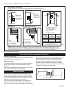
Mounting the Fireplace
CAUTION: DO NOT place fireplace on floor
or hard surface with bottom side down,
components could be damaged.
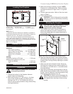
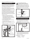
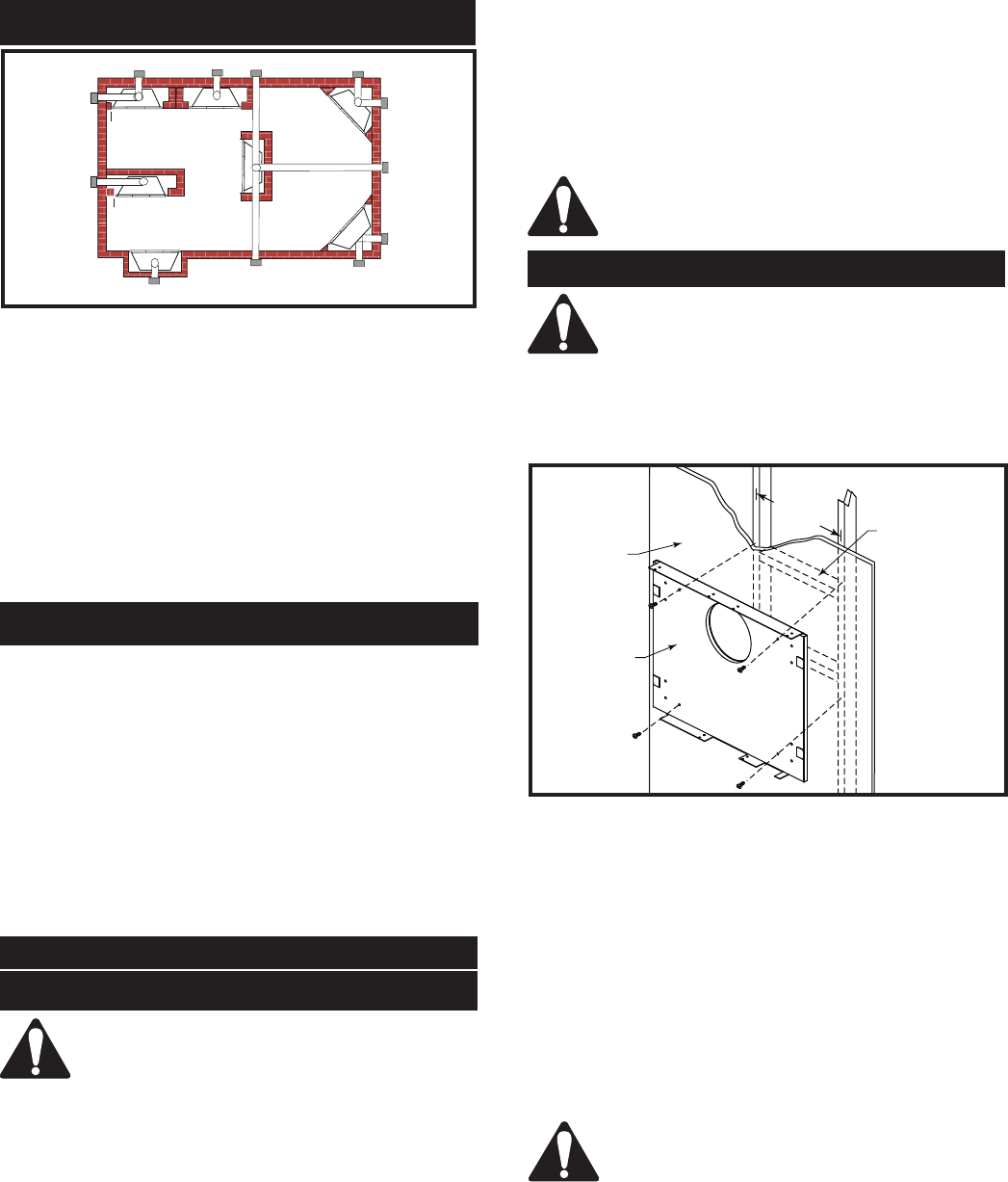
1. The DVR28 comes with a wall mount bracket to
secure the fireplace to the wall. Standoffs on the
back of the bracket allow for proper clearances to
combustibles. (Fig. 5)
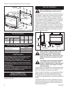
16” o.c.
(406 mm)
Firestop
Framing
(if required)
Finished
Wall
Wall Mounting
Bracket
FP1786
Fig. 5 Secure wall mounting bracket in desired location.
2. Align pipe clearance hole in wall mounting bracket
with through-the-wall clearance opening on noncom-
bustible wall or through firestop opening on combus-
tible walls.
3. Make sure wall mount bracket is level. Secure to
framing studs using mounting screws supplied. En-
sure framing is 16” (406 mm) o.c. to accommodate
mounting bracket.
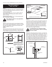
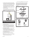
4. Align the top and bottom mounting holes of the fire-
place with the top and bottom holes of the mounting
bracket. Secure fireplace to mounting bracket using
sheet metal screws supplied. (Fig. 6)
CAUTION: Be careful to avoid damaging the
electric components located on the bottom of
the fireplace when securing to the mounting
bracket.