


14
20012301
Vermont Castings DVR28 Direct Vent Gas Fireplace
Below Grade Installations
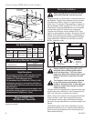
When it is not possible to meet the required vent ter-
minal clearances of 12” (305 mm) above grade level
a snorkel kit is recommended. This allows installation
depth of down to 7” (178 mm) below grade level. The
7” is measured from the center of the horizontal vent
pipe as it penetrates through the wall.
Ensure the sidewall venting clearances are observed.
If venting system is installed below ground, we recom-
mend a window well with adequate and proper drainage
to be installed around the termination.
If installing a snorkel, a minimum 24” (610 mm) vertical
rise is necessary. The maximum horizontal run with the
24” vertical pipe is 36” (914 mm). This measurement
is taken from the collar of the fireplace (or transition
elbow) to the face of the exterior wall. See the Sidewall
Venting Graph for extended horizontal run if the vertical
exceeds 24” (610 mm).
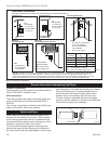
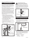
1. Establish vent hole through the wall. (Fig. 17)
2. Remove soil to a depth of approximately 16”
(406 mm) below base of snorkel. Install window
well (not supplied). Refill hole with 12” (305 mm) of
coarse gravel leaving a clearance of approximately
4” (102 mm) below snorkel. (Fig. 23)
3. Install vent system. Refer to Page 12.
4. Ensure a watertight seal is made around the vent
pipe coming through the wall.
5. Apply high temperature sealant caulking (supplied)
around the 4” and 7” snorkel collars.
6. Slide the snorkel into the vent pipe and secure to the
wall.
7. Level the soil to maintain a 4” (102 mm) clearance
below snorkel. (Fig. 23)
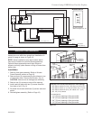
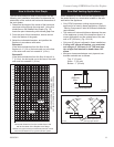
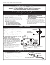
Zero Clearance Sleeve
(if required)
Screws
7TDVSNORK
(Snorkel)
4” Clear-
ance Min.
Window
Well
Gravel
Drain
Foundation Wall
*A minimum of 24” (610 mm)
vertical pipe must be installed
when using the 7TDVSNORK.
Firestop
7” Pipe
24” (610 mm )
Minimum *
BG404
Fig. 23 Below grade installation.
Do not backfill around snorkel.
A clearance of at lest 4” must be main
-
tained between the snorkel and the soil.
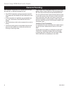
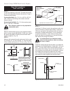
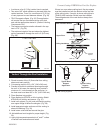
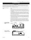
If the foundation is recessed, use recess brackets (not
supplied) for securing lower portion of the snorkel. Fas-
ten brackets to wall first, then secure to snorkel with self
drilling #8 x 1/2 sheet metal screws. It will be necessary
to extend vent pipes out as far as the protruding wall
face. (Fig. 24)
BG401
Snorkel
2/10/99 djt
Snorkel
Wall Screws
Sheet Metal
Screws
Foundation
Recess
Watertight Seal
Around Pipe
BG401
Fig. 24 Snorkel installation, recessed foundation.
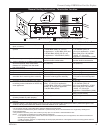
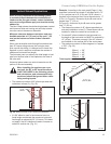
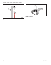
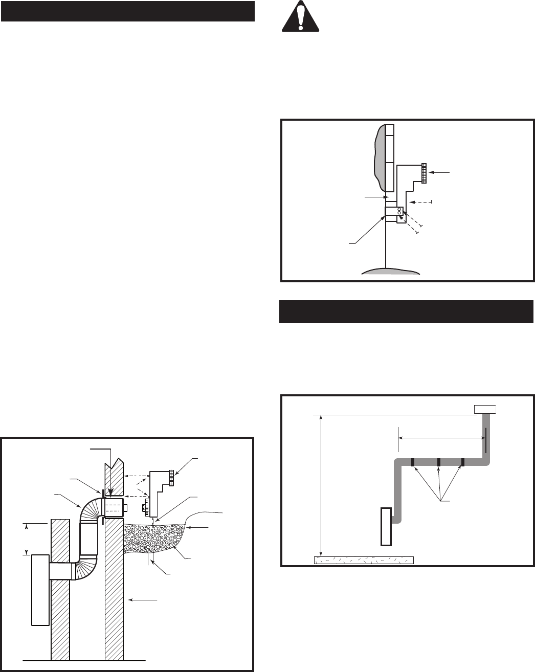
Vertical Through-the-Roof Application
This gas fireplace has been approved for:
• Vertical installations up to 40’ (12 m) in height. Up
to a 10’ (3 m) horizontal vent run can be installed
within the vent system using a maximum of two 90°
elbows. (Fig. 25)
Max. Height 40’
(12.2 m)
Min. Height 8’
(2.4 m)
Max. 10’ (3 m)
Support Straps
Every 3’ (914 mm)
FP1757
Fig. 25 Support straps for horizontal runs.
• Up to two 45° elbows may be used within the hori-
zontal run. For each 45° elbow used on the horizon-
tal plane, the maximum horizontal length must be
reduced by 18” (450 mm).
Example: Maximum horizontal length:
No elbows = 10’ (3 m)
1 x 45° elbow = 8.5’ (2.6 m)
2 x 45° elbows = 7’ (2.1 m)