


6
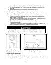
FIRE OR EXPLOSION HAZARD
LEAKING GAS CAN CAUSE FIRE OR EXPLOSION.
GAS LEAKS ARE FIRE AND EXPLOSION HAZARDS.
INJURY, DEATH, AND PROPERTY DAMAGE WILL RESULT.
If the installer smells gas, or suspects there is a gas leak, immediately refer to
the posted gas leak instructions. The posted instructions are provided by the
local gas supplier and supersede any other instructions.
E. Gas Supply for the SteamChef
If a gas leak is suspected, observe the following precautions in addition to the posted instructions:
• Do NOT light or start any appliance.
• Do NOT touch any electrical switch.
• Do NOT use any phone in the building.
• Immediately call the gas supplier from a phone away from the building.
• Follow the gas supplier’s instructions.
• If the gas supplier cannot be reached, call the fire department.
1. Gas Supply Requirements
• Gas supply type MUST match the type of gas shown on the rating plate.
• Gas supply pressure must NOT exceed 14” water column (1/2 psi), and fall within the acceptable
pressure range shown below when using 3/4” NPT line and a 1/2” NPT connection
• Natural gas pressure at 1000 BTU/CF must be between 7” – 14” water column.
• If the gas supply pressure exceeds 14” water column, a pressure regulating valve (pressure
regulator) must be installed in gas supply plumbing to reduce pressure to the SteamChef.
See Figure 3-1.
2. Installation of the Gas Supply Lines
The Installer / owner is responsible for furnishing and installing gas supply lines, valves,
regulators, and accessories.
When installing gas supply lines and accessories, observe the following:
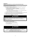
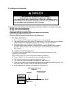
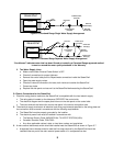
a. Refer to Figure 3-1 for the recommended layout of the gas supply lines.
b. Use a non-hardening pipe thread sealant resistant to LP gas.
c. The ½” NPT gas inlet is on the back of the SteamChef. See Figure 1-2
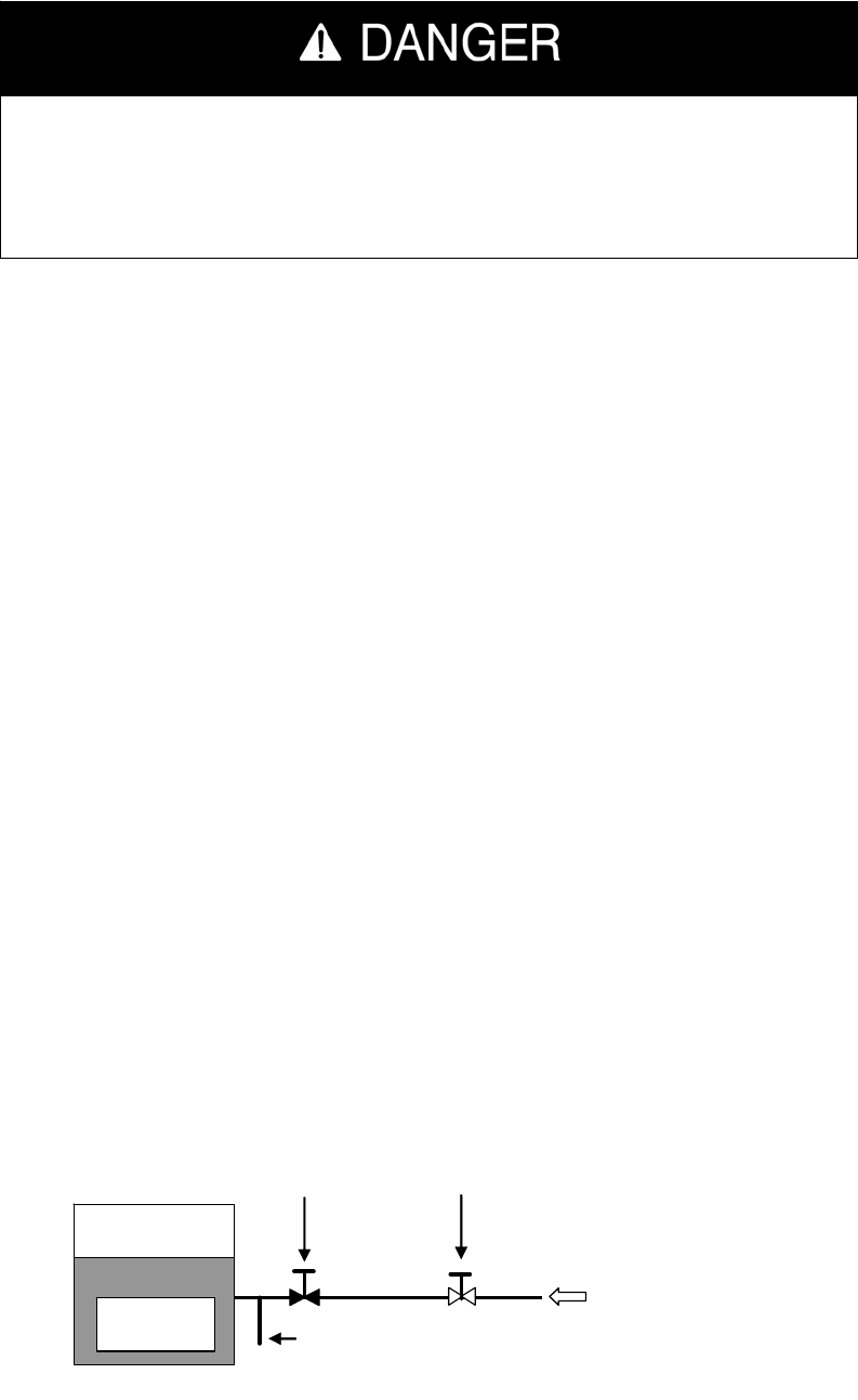
d. Install main manual shut off valve between gas supply and the SteamChef. See Figure 3-3. This
main manual shut off valve is called the “Main Manual Gas Valve.”
e. Install a sediment trap (drip leg) in gas supply line. See Figure 3-3.
SteamChef
GAS MANIFOLD
CONNECTION
DRIP LEG
MAIN GAS
SUPPLY
MAIN MANUAL
GAS VALVE
PRESSURE REGULATING
VALVE (IF REQUIRED)
Gas Supply Line Layout
Figure 3-3