


One Conair Drive ● Pittsburgh, PA 15202 ● 412-312-6000 ● FAX 412-312-6227 ● www.conairnet.com
0
0
0
0
0
0
0
0
0
B
A
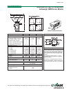
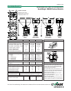
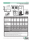
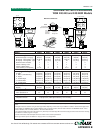
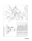
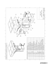
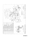
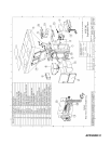
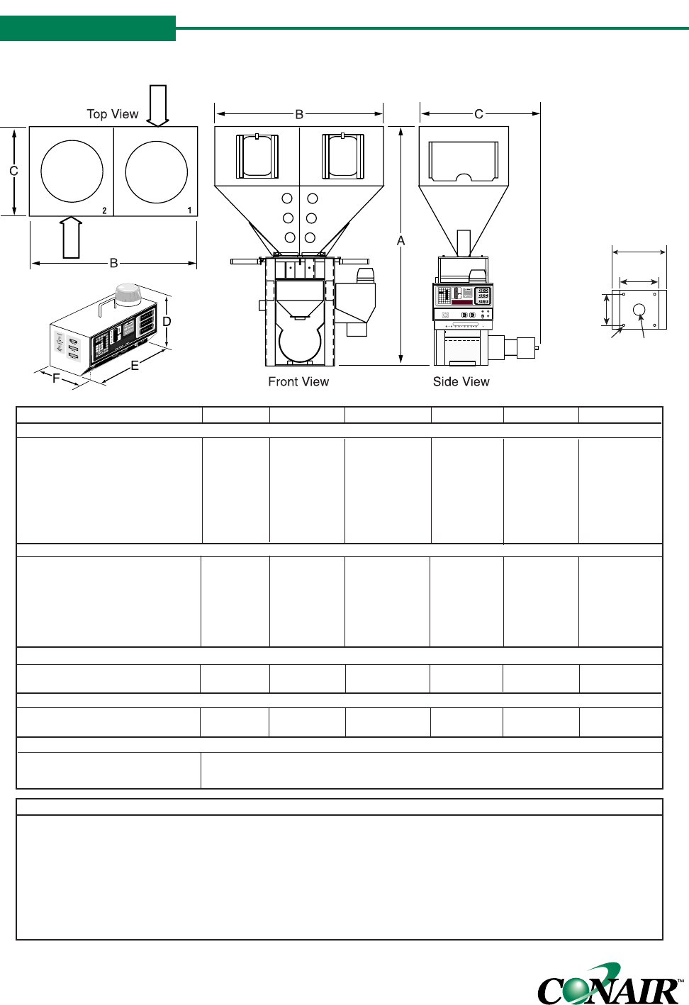
GRAVIMETRIC BATCH BLENDERS
WSB 220 and 420 Models
SPECIFICATION NOTES:
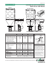
Each bin compartment will support a 12-inch to 15-inch loader or vacuum receiver.
*
Throughput rates are based on using no more than 5% additive or colorant material total in either the CAF3 compressed
air or F03 auger feeder. Always refer to the selection guide for specific throughput information.
† The optional butterfly control flow control valve adds 3.5 in. {88.9 mm} to the total height.We recommend using the flow
control valve when mounting the blender to a stand, surge bin or hopper.
‡ Feeders will increase width and depth dimensions. Please refer to feeder specifications.
§ Each additional auger feeder requires an additional 1 amp @ 120V or 0.5 amps @ 240V.
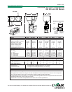
MODELS WSB220 WSB221 WSB222 WSB420 WSB421 WSB422
Performance characteristics
Batch size lbs {g} 4.4 {2000} 4.4 {2000} 4.4 {2000} 8.8
{4000}
8.8
{4000}
8.8
{4000}
Maximum throughput
lbs/hr {kg/hr}* 1239 {562} 575 {261} 540 {245} 1966 {892} 700 {318} 680 {308}
Bin capacity - each ft
3
{liter}
2.0 {56.6} 2.0 {56.6} 2.0 {56.6} 2.0 {56.6} 2.0 {56.6} 2.0 {56.6}
Maximum number of materials 2 3 4 2 3 4
Number of discharge valves 2 2 2 2 2 2
Number of additive feeders 0 1 2 0 1 2
Control software (# of components) 4 or 12 4 or 12 4 or 12 4 or 12 4 or 12 4 or 12
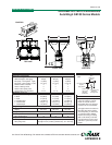
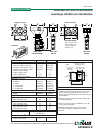
Dimensions inches {mm}
A - Height above mounting plate
†
48 {1217.9} 48 {1217.9} 48 {1217.9} 54 {1370.3} 54 {1370.3} 54 {1370.3}
B - Width
‡
34.4 {873.8} 34.4 {873.8} 34.4 {873.8} 34.4 {873.8} 34.4 {873.8} 34.4 {873.8}
C - Depth
‡
24.75 {628.6} 24.75 {628.6} 24.75 {628.6} 24.4 {619.8} 24.4 {619.8} 24.4 {619.8}
D - Controller height 11.25 {285.75} 11.25 {285.75} 11.25 {285.75} 11.25 {285.75} 11.25 {285.75} 11.25 {285.75}
E - Controller width 12.25 {311.15} 12.25 {311.15} 12.25 {311.15} 12.25 {311.15} 12.25 {311.15} 12.25 {311.15}
F - Controller depth 8.19 {208.03} 8.19 {208.03} 8.19 {208.03} 8.19 {208.03} 8.19 {208.03} 8.19 {208.03}
Weight lbs {kg}
Installed 220 {100} 260 {118} 300 {136} 245 {111} 285 {129} 325 {147}
Shipping 325 {147} 265 {120} 405 {183} 350 {159} 390 {177} 430 {195}
Voltage Total amps
§
120V/1 phase/50-60 Hz 4.8 4.8 4.8 4.8 4.8 4.8
240V/1 phase/50-60 Hz 2.5 2.5 2.5 2.5 2.5 2.5
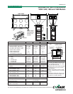
Compressed air requirements
Discharge valves 80 psi @ 0.2 ft
3
/min. {5.5 bars @0.09 liters/sec}, 1/4 in. NPT fitting
Compressed air feeder 40 psi @ 2 ft
3
/min. {2.8 bars @0.94 liters/sec}, 1/4 in. NPT fitting
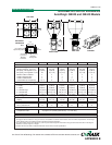
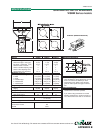
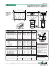
(4) 9/16 in.
{14.3 mm}
diameter
bolt holes
3 in. {76.2 mm}
diameter
through hole
8 in.
{203.2 mm}
square bolt
pattern
10 in.
{254 mm}
14 in.
{355.6 mm}
MOUNTING INTERFACE
CONTROL
SPECIFICATIONS
TPBS002/1199
IBO4
APPENDIX B