


One Conair Drive ● Pittsburgh, PA 15202 ● 412-312-6000 ● FAX 412-312-6227 ● www.conairnet.com
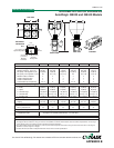
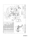
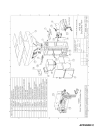
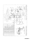
MODELS WSB1840 WSB1850 WSB1860
Performance characteristics
Batch size lbs {g} 39.7 {18000} 39.7 {18000} 39.7 {18000}
Maximum throughput lbs/hr {kg/hr}* 4114 {1866} 3160 {1433} 2566 {1164}
Bin Capacity - Main Ingredient ft
3
{liter} 6.7 {189.7} 6.7 {189.7} 3.8 {107.6}
Bin Capacity - Minor Capacity ft
3
{liter} 3.8 {107.6} 3.8 {107.6} 3.8 {107.6}
Maximum number of materials 8 9 10
Number of discharge valves 4 5 6
Number of additive feeders up to 4 up to 4 up to 4
Control Software (# of components) 4 or 12 12 12
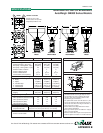
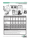
Dimensions inches {mm}
A - Height above mounting plate 93 {2362.2} 93 {2362.2} 93 {2362.2}
B - Width
†
56.25 {1428.8} 56.25 {1428.8} 56.25 {1428.8}
C - Depth
†
34.4 {873.8} 34.4 {873.8} 34.4 {873.8}
D - Controller height 11.25 {285.75} 11.25 {285.75} 11.25 {285.75}
E - Controller width 12.25 {311.15} 12.25 {311.15} 12.25 {311.15}
F - Controller depth 8.19 {208.03} 8.19 {208.03} 8.19 {208.03}
Weight lbs {kg}
Installed 730 {331} 730 {331} 730 {331}
Shipping 850 {385.5} 850 {385.5} 850 {385.5}
Voltage Running load amps
‡
110V/1 phase/60hz (control) 0.3 0.3 0.3
220V/1 phase/60hz (mixer) 8.2 8.2 8.2
220V/1 phase/60hz (control) 0.2 0.2 0.2
220V/1 phase/60hz (mixer) 8.2 8.2 8.2
220V/1 phase/50hz (control) 0.2 0.2 0.2
220V/3 phase/50hz (mixer) 4.4 4.4 4.4
400V/3 phase/50hz (mixer) 2.2 2.2 2.2
Compressed air requirements
Discharge valves 80 psi @ 0.2 ft
3
/min {5.5 bars @ 0.09 liters/sec}
1/4 in. NPT fitting
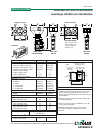
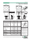
Maximum loader sizes
§
Number of 20 inch loaders 2 2 3
Number of 15 inch loaders 4 5 6
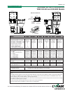
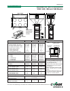
GRAVIMETRIC BATCH BLENDERS
WSB 1840, 1850 and 1860 Models
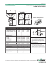
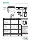
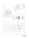
MOUNTING INTERFACE
SPECIFICATION NOTES:
* Maximum throughput rates are based
on using all dispense valves and 35
lb/ft
3
pelletized material. Use of feed-
ers will reduce this rate.
† Feeders will increase width and depth
dimensions. Please refer to feeder
specifications.
‡ Each auger feeder requires an addi-
tional 1 amp @ 120V or 0.5 amp @
240V.
§ Maximum loader sizes may be used
only when the loader is adjacent to
loaders of a smaller diameter.
(4) 9/16 in. {14.3 mm}
diameter bolt holes
4 in. {101.6 mm}
diameter
through hole
8 in. {203.2 mm}
square bolt pattern
15 in. {381 mm}
14.5 in.
{368.3 mm}
16 in.
{406.4 mm}
20 in. {508 mm}
SPECIFICATIONS
TPBS005/0700
IB04
0
0
0
0
0
0
0
0
0
A
C
C
B
CONTROL
Note: loader
configuration
same for all
models
APPENDIX B