


16
GAS REQUIREMENTS
Verify the type of gas supplied to the location. The cooktop is shipped from the factory set up and adjusted for
Natural Gas or LP (propane), depending on the specific model ordered.
Verify that the cooktop is compatible
with gas supply at the installation site before proceeding further.
Return the cooktop to the dealer if the unit is
not set for the gas supplied at the site.
NATURAL GAS
■ Connection: 1/2” NPT Minimum 5/8” dia. flex line. ■ Supply Pressure: 6” to 14” W.C.
LP GAS
■ Connection: 1/2” NPT Minimum 5/8 dia. flex line. ■ Supply Pressure: 11” to 14” W.C.
A regulator is required at the LP source to provide a maximum of 14” W.C. to the cooktop regulator.
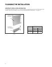
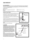
HOOK-UP TO GAS SUPPLY
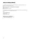
A manual valve must be installed external to the appliance, in an
accessible location from the front for the purpose of shutting off the
gas supply (Fig. 11). Make sure the gas supply is turned off at the
wall valve before connecting the appliance. The gas supply
connections should be made by a qualified technician and in
accordance with local codes or ordinances. In the absence of a local
code, the installation must conform to the latest edition of National
Fuel Gas Code ANSI Z223.1.
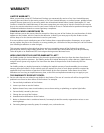
To prepare the unit for connection to the gas supply, thread the
supplied 1/2” pipe nipple into the elbow on the end of the manifold.
The elbow is located inside the chassis of the unit, on the end of the
manifold, facing down. See fig.12. It is accessible through the
square cutout in the left rear corner of the chassis bottom. Connect
the outlet of the regulator to the exposed end of the nipple, connect
the flex line from the gas supply to the inlet side of the regulator.
NOTE:
Pipe seals must be used on all pipe threads.
CAUTION:
T
he appliance must be isolated from the building’s gas
supply piping system by closing its individual manual
shut-off valve during any pressure testing of the gas
supply piping sy
stem at test pressures equal to or less
than 1/2 psig (3.5kPa.). The appliance and its
individual shut-off valve must be disconnected from
the gas supply piping sy
stem during any pressure
testing of the system at the test pressures in excess of
1/2 psig (3.5kPa.). When checking the manifold gas
pressure, the inlet pressure to the regulator should be
at least 7.0”W.C. for natural gas or 12.0”for LP.
NOTE:
The arrow on the regulator indicating direction of gas
flow should be pointing towards the unit. The flex line
for the gas supply must be metal and be approved by an
approved certif
ying agenc
y (
A
GA, CGA, or UL). Never use
a hose made of rubb
er or other synthetic material, as the
heat may cause the hose t
o melt and dev
elop leaks
.
GAS HOOK-UP
Fig. 12
*Installation must conform with
local codes or with the National
Fuel Gas Code ANSI Z223.1 or
the CAN/CGA-B149.2 Propane
Installation Code
Coupling
1/2 NPT black
1/2 NPT
Close Nipple
Regulator
LP/NG (included)
Adapter 1/2 NPT
to 3/8 flare fitting
Do not put threading
compound on these
threads
Bottom of unit
Threading compound
must be resistant to LP gas
1/2 x 5" NPT
Close
Nipple
Installer supplied shut-off
valve must be easily
accessible*
Fig. 11
Flex Line to Cooktop
Manual Shut-Off
Valve must be
Easily Accessible
!