


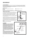
ELECTRICAL CONNECTIONS
15
ELECTRICAL REQUIREMENTS
■
120 VAC, 60 Hz., single phase
■
CP-48: 15 Amp. Max. (use 15 Amp. circuit)
■
CP-36: 15 Amp. Max. (use 15 Amp. circuit)
Always disconnect electric supply cord from the wall outlet or service
disconnect before servicing this appliance. Observe all governing codes
and ordinances when grounding, in absence of which, observe National
Electrical Code ANSI / NFPA No. 70.
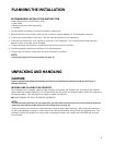
RECOMMENDED GROUNDING METHOD
This appliance is factory equipped with a power supply cord with a
three-prong grounding plug (with polarized parallel blades). It must be
plugged into a mating grounding type receptacle, connected to a
correctly polarized 120 Volt circuit. If the circuit does not have a
grounding type receptacle, it is the responsibility and obligation of the
installer to have the existing receptacle changed to a properly grounded and polarized receptacle in accordance
with all applicable local codes and ordinances by a qualified electrician. In the absence of local codes and
ordinances, the receptacle replacement shall be in accordance with the National Electrical Code.
Note:
The third prong should not, under ANY circumstances, be cut or removed.
Receptacle Box
Cover Plate
Three Prong
Receptacle
Three
Prong
Plug
Fig. 10
Fig. 9
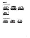
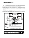
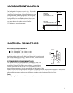
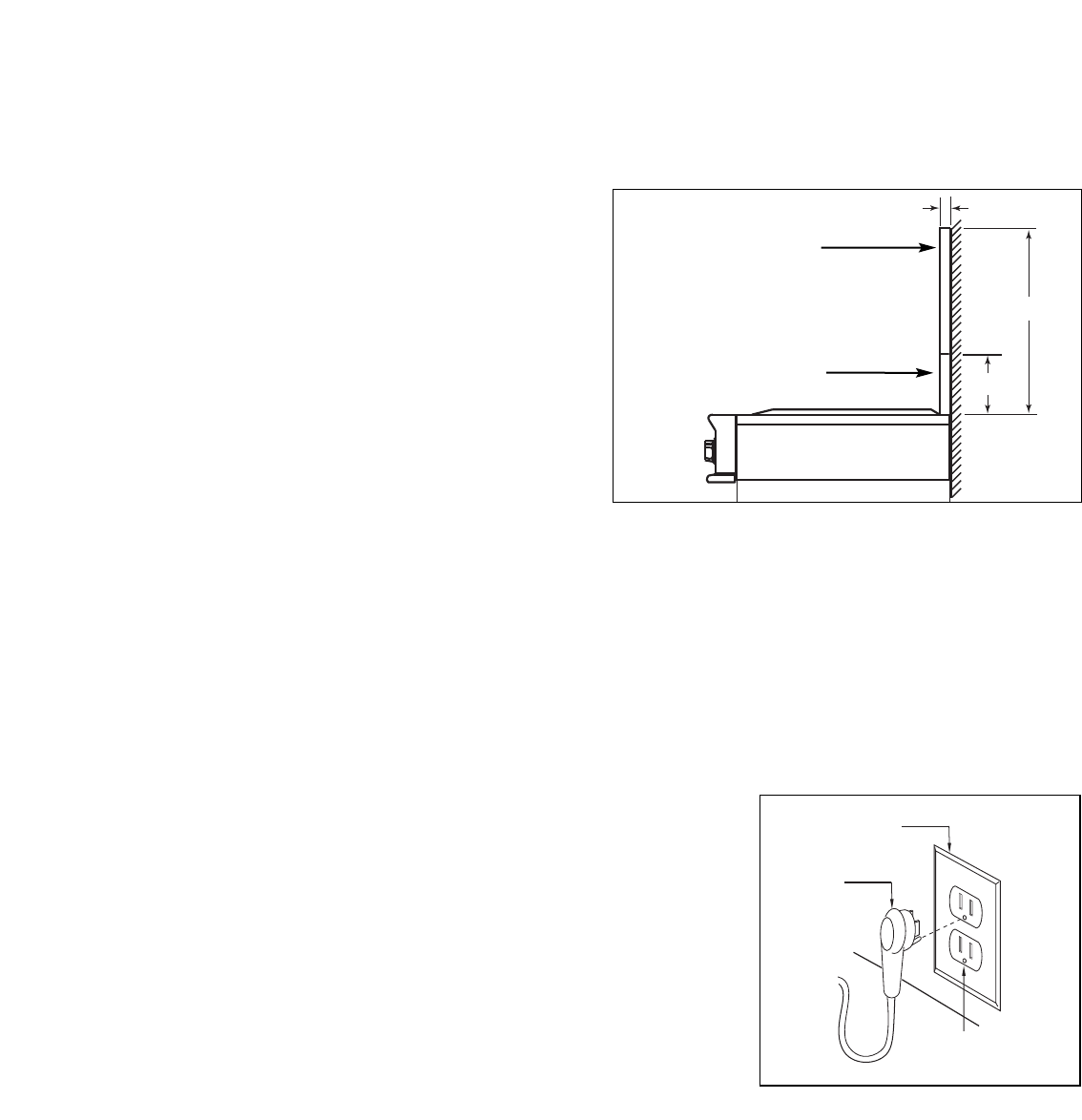
BACKGUARD INSTALLATION
T
he backguard is located as shown in Fig. 9. Secure the
backguard to the wall behind the range. Specific
instructions for installation of the full backguard or low
backguard can be found packaged with the backguard.
See also page 8, “Planning The Installation” section. A
b
ackguard must be installed when there is less than a
12” clearance between combustibles and the back of
the range (above the cooking surface). See fig. 8.
DCS backguards are sold separately.
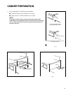
12"
30"
15/16"
Wall Mount
Full Backguard
(
Model #’s BGC-3036, BGC-3048)
Wall Mount
Low Backguard
(
Model #’s BGC-1236, BGC-1248)