


17
TEST AND ADJUSTMENTS
WARNING:
F
or warranty coverage, DCS requires that burner adjustments be made by a
qualified technician at the time of installation. Extreme care should be used
when adjustments are made after installation.
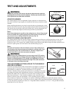
COOKTOP BURNERS
The cooktop burners are not adjustable. Proper operation is achieved when
the correct orifices for gas supply are installed at the factory, based on model
ordered.
When installing the burner port ring, be sure that the two locating pins in the
bottom side of the brass port ring are properly aligned with the locating notch
and center holes on the top side of the simmer ring. Incorrect alignment will
produce a potentially dangerous flame and poor burner performance.
Note:
No air shutter adjustment is possible on the cooktop burners. Burner flames should
be blue and stable with no yellow-tipping (some yellow-tipping is normal with LP
gas), excessive noise, or lifting of flame from the burner (Fig. 13).
COOKTOP BURNER LIGHTING NOTE
The cooktop burners have an infinite number of heat settings and there are no fixed positions on the control
knobs between HI and LO. To turn the cooktop burner on, push in on the control knob and turn it counter-
clockwise to the “LITE” position. An audible clicking sound will be heard. When the gas has been ignited by the
electronic spark igniter, turn the knob to the desired setting (Fig. 14).
Note:
The igniter will continue to click until a flame is present. If the cooktop burner
does not ignite, check the spark igniter by listening for a clicking sound. If you
do not hear the igniter click, turn off the burner. Check for a tripped circuit
breaker, blown fuse, or poor wire connection to the igniter.
WARNING:
When turning on any cooktop burner, be sure to stop at the “LITE”position
bef
or
e turning the burner t
o a flame setting f
or cooking. If the burner is not
lit and it is turned beyond the “LITE”position, to HI, MEDIUM, or LO, there
will be a burst of flame when the burner does ligh
t
. This could cause burns
or damage t
o the surr
ounding c
oun
t
er
top.
THIS ADJUSTMENT SECTION APPLIES TO THE GRIDDLE
AND GRILL BURNERS.
Check for the proper burner flame characteristics and adjust air shutters if
necessary (fig. 15). Each valve and air shutter is individually tested and
adjusted prior to shipment. Normally adjustment is not required,
however, vibration during transit, gas conversion or variations in the local
gas supply may make minor adjustments necessary. Burner flames should
be blue and stable with no yellow tips, excessive noise or lifting of the
flame from the burner. If any of these conditions exist, check that the air
shutter or burner ports are not blocked. If this condition persists, adjust
the air shutter as required. If the flame is too yellow, indicating insufficient air, adjust the shutter counter-
clockwise to increase air inlet. If the flame is noisy or tends to lift away from the burner, indicating too much
air, turn the shutter clockwise to reduce air. The griddle flames should be 1-1/2" to 2". The grill burner flames
should be 3/8” to 5/8” (fig. 16).
1-1/2"
COOKTOP BURNER
FIG. 13
FIG. 14
SIM
LO
LITE
HI
OFF
Fig. 15
1-1/2" ~ 2"
Typical Section of Proper Flame
3/8" ~ 5/8"
(Grill)
(Griddle)
Fig. 16
Typical Section of Proper Flame
Griddle
1-1/2” – 2”
3/8” – 5/8”
Grill
air shutter