


14
CAST IRON STOVE AND BURNER SYSTEM
106706
SUN VALLEY STOVE COMPANY
For more information, visit www.desatech.com
Pressure Testing Gas Supply
Piping System
Test Pressures In Excess Of 1/2 PSIG
(3.5 kPa)
1.
Disconnect appliance with its appliance
main gas valve (control valve) and
equipment shutoff valve from gas
supply piping systems. Pressures in
excess of 1/2 psig (3.5 kPa) will damage
burner system gas regulator.
2. Cap off open end of gas pipe where
equipment shutoff valve was con-
nected.
3. Pressurize supply piping system by ei-
ther opening propane/LP supply tank
valve for propane/LP gas burner sys-
tem or
opening main gas valve located
on or near gas meter for natural gas
burner system,
or using compressed air.
4. Check all joints of gas supply piping
system. Apply commercial leak test so-
lution to all gas joints. Bubbles forming
show a leak. Correct all leaks at once.
5. Reconnect burner system and equip-
ment shutoff valve to gas supply. Check
reconnected fittings for leaks.
CHECKING GAS
CONNECTIONS
WARNING: Test all gas pip-
ing and connections for leaks
after installing or servicing. Cor-
rect all leaks at once.
WARNING: Never use an open
flame to check for a leak. Apply
commercial leak test solution to all
gas joints. Bubbles forming show
a leak. Correct all leaks at once.
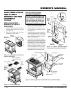
Installation Items Needed
• 5/16" hex socket wrench or nut-driver
• sealant (resistant to propane/LP gas, not
provided)
1. Open lower door panel.
2. Route flexible gas line (provided by
installer) from equipment shutoff valve
to burner system. Route flexible gas
supply line through slot in stove bot-
tom and attach to valve.
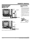
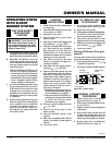
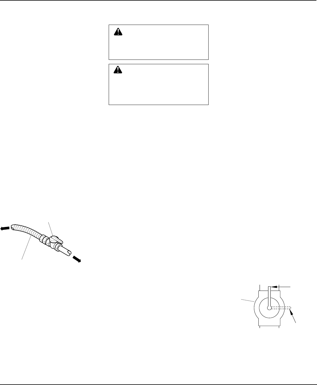
3. Attach a 45° flare union gas connector
to flexible gas line from gas supply (see
Figure 32). Connect flare union to flex-
ible gas line attached to gas regulator
of fireplace (see Figure 32).
4. Check all gas connections for leaks. See
Checking Gas Connections.
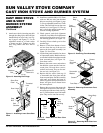
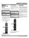
CONNECTING STOVE AND
BURNER SYSTEM TO GAS
SUPPLY
Flexible Gas Line from
Equipment Shutoff Valve
Provided by Installer
Equipment
Shutoff Valve
To Gas
Supply
(Natural)
Figure 32 - Attaching Flexible Gas Lines
Together
STOVE AND B-VENT
BURNER SYSTEM
INSTALLATION
Continued
To External
Regulator
(Propane/LP)
Test Pressures Equal To or Less Than
1/2 PSIG (3.5 kPa)
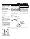
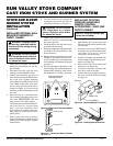
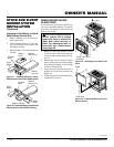
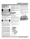
1. Close equipment shutoff valve (see
Figure 33).
2. Pressurize supply piping system by ei-
ther opening propane/LP supply tank
valve for propane/LP gas burner sys-
tem or
opening main gas valve located
on or near gas meter for natural gas
burner system,
or using compressed air.
3. Check all joints from propane/LP sup-
ply tank or gas meter to equipment
shutoff valve (see Figure 34 for pro-
pane/LP or Figure 35 for natural). Ap-
ply commercial leak test solution to all
gas joints. Bubbles forming show a
leak. Correct all leaks at once.
Pressure Testing Burner
System Gas Connections
1. Open equipment shutoff valve (see Fig-
ure 33).
2. Open propane/LP supply tank valve for
propane/LP burner system or main gas
valve located on or near gas meter for
natural gas burner system.
3. Make sure control knob of burner sys-
tem is in the OFF position.
4. Check all joints from equipment shutoff
valve to thermostat gas valve (see Fig-
ure 34 for propane/LP or Figure 35 for
natural, page 15). Apply commercial
leak test solution to all gas joints.
Bubbles forming show a leak. Correct
all leaks at once.
5. Light burner system (see Lighting In-
structions, page 19). Check all other in-
ternal joints for leaks.
6. Turn off burner system (see To Turn Off
Gas to Appliance, page 19).
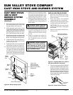
Figure 33 - Equipment Shutoff Valve
ON
POSITION
OFF
POSITION
Open
Closed
Equipment
Shutoff
Valve