


15
106706
OWNER’S MANUAL
For more information, visit www.desatech.com
STOVE AND B-VENT
BURNER SYSTEM
INSTALLATION
Continued
Continued
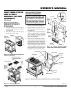
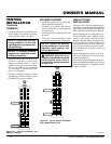
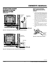
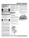
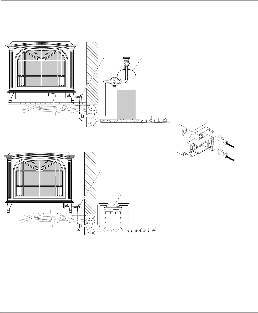
Figure 34 - Checking Gas Joints for Propane/LP Gas Burner System
Propane/LP
Supply Tank
Equipment
Shutoff
Valve
Gas Valve
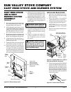
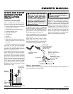
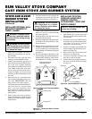
Equipment
Shutoff Valve
Gas Valve
Gas Meter
Figure 35 - Checking Gas Joints for Natural Gas Burner System
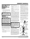
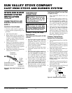
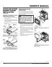
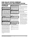
Figure 36 - Control Valve Terminals
To Control
Switch or
Optional
Accessory
INSTALLING OPTIONAL
WALL MOUNTED SWITCH
GWMS2
1. Connect one terminal of 25 ft. wire for
the wall switch to the TPTH terminal
on the valve. Connect remaining wire
terminal to the TH terminal on the valve.
Make sure that the wire terminals are in
the positions on the unit as pictured in
Figure 36. If wires are not connected as
shown, the switch will not work.
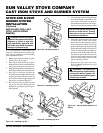
2. Route the 25 ft. wire through openings
provided on the sides of the burner sys-
tem to a convenient location to mount
your switch.
3. Connect one bare wire end to each of the
terminals of the GWMS2 wall switch.
4. Install the wall switch and cover in the
wall.