


7
106706
OWNER’S MANUAL
For more information, visit www.desatech.com
CAST IRON STOVE
AND B-VENT
BURNER SYSTEM
ASSEMBLY
Continued
Continued
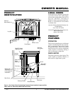
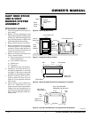
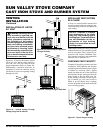
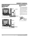
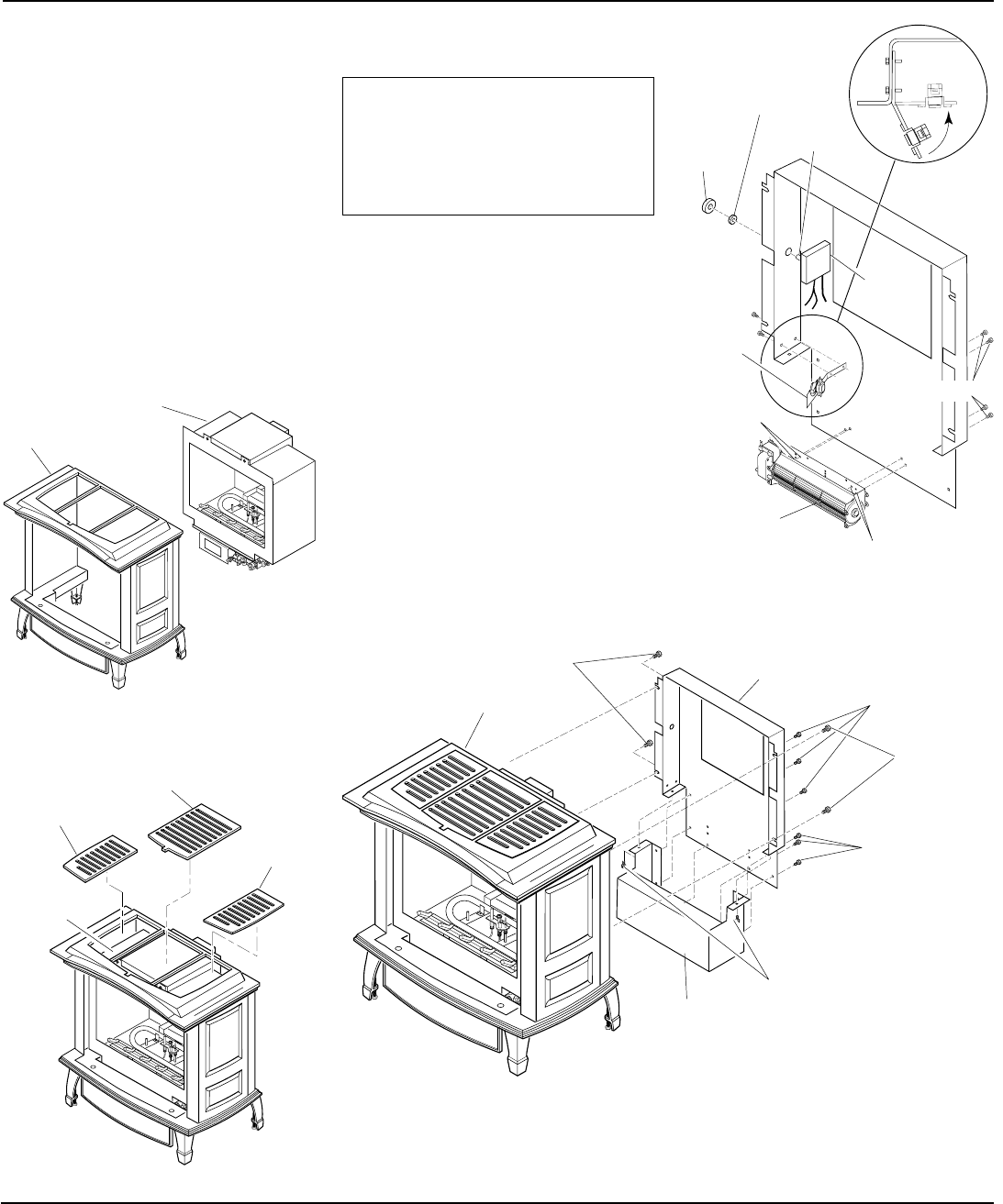
INSTALLING B-VENT
BURNER SYSTEM INTO
STOVE BODY
1. Carefully lift burner system and place
into stove body from the rear of stove
(see Figure 16).
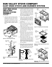
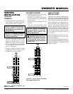
2. Place the left, right, and center grate
top into top of stove body.
L
O
H
I
P
I
L
O
T
O
F
F
O
N
Burner
System
Cast Iron
Stove Body
Figure 16 - Installing Burner System into
Cast Iron Stove Body
Figure 17 - Installing Top Grates
Burner
System
in Stove
Body
Left Top Grate
Center Top Grate
(Included with Stove
Body)
Right
Top
Grate
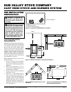
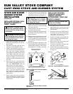
NOTICE: If installing blower in an
existing stove burner system with
gas connections, shut off gas sup-
ply and disconnect burner sys-
tem from gas supply. Contact a
qualified service person to do this.
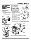
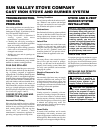
Figure 18 - Removing Rear Cover and Bottom Cover from Stove Body
INSTALLING OPTIONAL
BLOWER ACCESSORY
1. Remove 4 hex screws securing rear cover
to back of stove body (see Figure 18).
2. Separate bottom cover from rear cover
by loosening the 8 mounting screws
(see Figure 18).
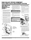
3. Align the holes in the top mounting tabs
of blower with the holes in wall of rear
cover. Using the 4 screws provided,
mount blower and tighten screws se-
curely (see Figure 19).
4. Attach thermal switch and bracket to
inside rear cover wall with two hex head
screws provided as shown. After secur-
ing bracket to rear cover, carefully bend
along existing bend line on bracket to
almost a 90° angle (see Figure 19). This
will allow thermal switch to be posi-
tioned against stove rear wall and sense
temperature when in operating mode.
Stove Body
Rear Cover
Bottom Cover
Hex
Screws
Mounting
Screws
Mounting
Screws
Hex Screws
Mounting
Screws
Figure 19 - Blower Assembly, Speed
Control, and Thermal Switch Locations
Speed
Control
Blower
Control
Knob
Locknut
Blower
Assembly
Mounting
Holes
Thermal
Switch
and
Bracket
Control
Shaft
TOP VIEW
Mounting
Holes
Screws