


8
CAST IRON STOVE AND BURNER SYSTEM
106706
SUN VALLEY STOVE COMPANY
For more information, visit www.desatech.com
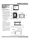
CAST IRON STOVE
AND B-VENT
BURNER SYSTEM
ASSEMBLY
Continued
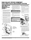
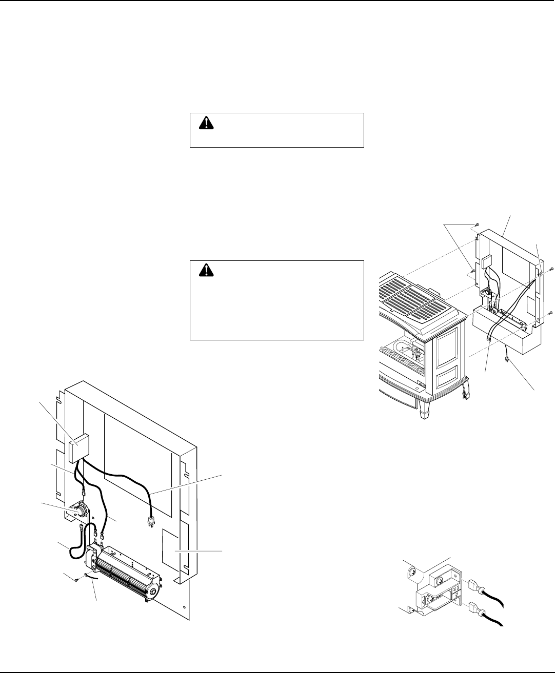
INSTALLING REAR COVER
1. Place rear cover behind stove body.
Rear cover will rest on the bottom ledge
of the stove body.
2. Place wire harness from ON/OFF
switch under the cast of stove body.
3. Using screws provided, attach rear cover
to back of stove body. See Figure 21.
IMPORTANT:
This rear cover must be
securely in place before venting pipes
are installed.
4. Open lower door panel on front of stove
to locate valve.
WARNING: Never touch the
blower wheel while in operation.
WARNING: Failure to position
the parts in accordance with sup-
plied diagrams or failure to use
only parts specifically approved
with this heater may result in dam-
age or personal injury.
5. Place speed control on left inside of rear
cover and push the plastic control shaft
through opening (see Figure 19).
6. While supporting speed control, secure
control shaft with lock nut by pushing and
turning lock nut with pliers clockwise
until tight against the side of rear cover.
Place control knob provided onto shaft.
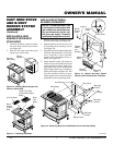
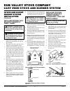
7. Place the green ground wire between the
bottom hole on the blower assembly and
the hex screw and tighten (see Figure 20).
8. Connect the blue wire to the blower as-
sembly and one side of the thermal
switch (see Figure 20).
9. Connect the black wire to the other side
of the thermal switch (see Figure 20).
10. Connect the white wire to the other ter-
minal on the blower motor assembly
(see Figure 20). Make sure the thermal
switch has been properly installed to fit
against back of fireplace insert after the
rear cover assembly has been reinstalled.
11. Make sure all wire connections to termi-
nals on blower motor and thermal switch
are securely attached and that the screw
retaining the green ground wire is tight.
12. Check to make sure that the power cord
is completely clear of the blower wheel
and that there are no foreign objects in
blower wheel.
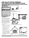
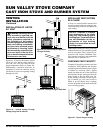
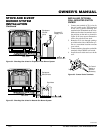
Figure 21 - Installing Rear Cover (Shown
with Optional Blower Accessory)
Rear Cover (Shown
with Optional Blower)
Hex
Screws
13. Peel off the backing paper and stick the
supplied wiring diagram decal on the
inside of rear cover as shown (see Fig-
ure 20).
14. Connect or reconnect gas supply fol-
lowing instructions in Connecting
Stove and Burner System to Gas Sup-
ply, page 14.
Blower
Power
Cord
ON/OFF
Switch
Wire
Harness
ON/OFF
Switch
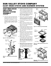
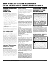
Figure 22 - Control Valve Terminals
To Control
Switch
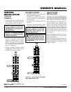
Figure 20 - Blower Wiring Layout
Green Ground Wire
Wiring
Diagram
Decal
Speed
Control
Box
Black
Wire
White
Wire
Blue
Wire
Power Cord
(Route Through
Plastic Bushing in
Bottom Cover When
Assembled)
Screw
Thermal
Switch
5. Connect one wire terminal from ON/OFF
switch to the THTP terminal on the valve.
Connect remaining wire terminal to the
TH terminal on the valve. Make sure that
the wire terminals are in the positions on
the unit as pictured in Figure 22. If wires
are not connected as shown, the ON/OFF
switch will not work.