


12
DOMETIC® RM7030/RM7732
Refrigerators
DIAGNOSTIC SERVICE MANUAL
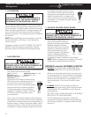
5.7 FUSES
A. RM7030 (Product No. 921890201 & 921890301)
The fuse is to protect the circuit board. To check the
fuse, remove it from the holder and do a continuity
check. If no continuity, replace it with a proper 3-amp
time delay fuse.
B. RM7030 (Product No. 921890401) and RM7732
The fuses are to protect the circuit board and the
integrity of the heater circuit(s) against shorts.
The 3-amp DC fuse is designed to protect the circuit
board from internal shorts. The 5-amp AC fuse is
designed to protect the integrity of the AC heater circuit
from shorts.
To check the fuses, remove from the holder and do a
continuity check. If no continuity, replace with a proper
amperage fuse.
NOTE: Determine the cause of the fuse failure and
correct before replacing fuse.
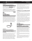
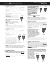
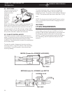
7-PIN
CONNECTOR
6-PIN
CONNECTOR
10-PIN
CONNECTOR
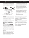
5.8 UPPER CIRCUIT BOARD
RM7030 (Product No. 921890201 & 921890301)
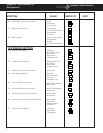
A. ON-OFF SWITCH
NOTE: The following checks should be made on the
upper circuit board and harness assembly BEFORE
replacing the upper circuit board or wiring
harness. The checks are to be done with the
wiring harness REMOVED from the lower
circuit board.
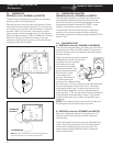
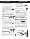
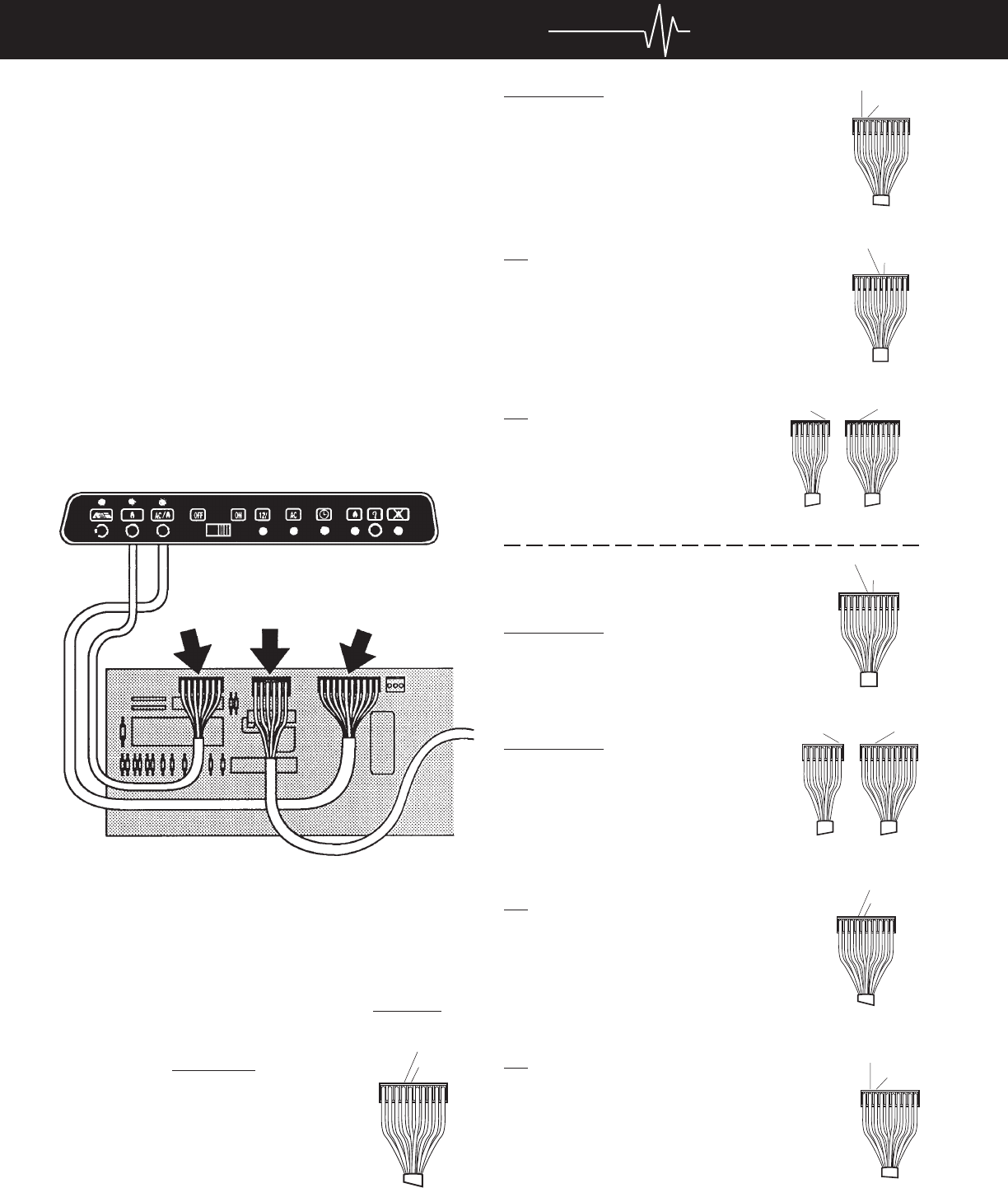
With the switch in the "ON" position:
CONTINUITY should be indicated be-
tween the orange terminal to the yellow
terminal on the 10-pin connector.
ORANGE
YELLOW
10 PIN
CONTINUITY should be indicated between
the brown terminal to the red terminal on the
10-pin connector.
BROWN
RED
10 PIN
YELLOW
GREEN
10 PIN
RED
BLUE
10 Pin7Pin
NO continuity should be indicated between
the yellow terminal to the green terminal
on the 10-pin connector.
NO continuity should be indicated
between the red terminal on the 10-
pin connector to the blue terminal
on the 7-pin connector.
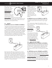
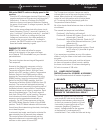
With the switch in the "OFF"
position:
CONTINUITY should be indicated
between the yellow terminal to the green
terminal on the 10-pin connector.
YELLOW
GREEN
10 PIN
RED
BLUE
10 Pin7Pin
CONTINUITY should be indicated
between the red terminal on the 10-
pin connector to the blue terminal on
the 7-pin connector.
NO continuity should be indicated
between the orange terminal to the
yellow terminal on the 10-pin connector.
NO continuity should be indicated between the
brown terminal to the red terminal on the 10-
pin connector.
NOTE: If any of these checks on the ONOFF
switch are not correct, verify the wire harness
has continuity. If the wire harness is good,
replace the upper circuit board.
BROWN
RED
10 PIN
ORANGE
YELLOW
10 PIN