


15
DIAGNOSTIC SERVICE MANUAL
DOMETIC® RM7030/RM7732
Refrigerators
DIAGNOSTIC MODE
NOTE: The PAL tester will allow for proper
testing of the integrity of the upper and lower
circuit boards. PAL is available from your Dometic
parts distributor.
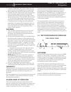
This control system has an integral Diagnostic/
Test sequence.
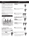
Access to the diagnostic sequence unit is by
means of the ON/OFF Power Switch and the
Temperature Selector Switch. With the Power
Switch in the OFF position, hold the Temperature
Selector Switch in the DOWN position. While
keeping the Temperature Selector Switch in the
DOWN position, move the main power ON/OFF
Switch to the ON (DOWN) position. Hold the
Temperature Selector Switch DOWN for three (3)
seconds. The control will indicate that the diag-
nostics have been entered by illuminating each of
the Mode Indicator Lamps and the Temperature
Indicator Lamps one at a time in sequence. Each
lamp is illuminated twice. The Check Lamp will
then flash ON and OFF and #1 position Tempera-
ture Indicator will remain illuminated. The test
sequence can be operated automatically or
manually. For AUTO step sequence, press the
AUTO/GAS Mode Selector Switch to the DOWN
position. The AUTO Mode Indicator will illuminate.
If each lamp illuminates during the check, the display
circuit board is good.
In automatic test mode, each load is activated for
approximately four (4) seconds then released.
The control system will automatically exit the
diagnostic sequence in approximately four (4)
minutes or when power is turned OFF.
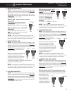
The Temperature Indicator Lamps are used to
indicate which part of the control system is being
tested. When position #1 is illuminated, the
control is in an idle position with all output loads
off. To activate the first load simply push the
Temperature Selector Switch.
All of the checks listed below are done on the lower
circuit board.
The manual test sequence is as follows:
Position #1: Idle Position, all loads off.
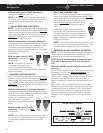
Position #2: Activate AC Heater. Check for AC volts
at terminals J7 and J8.
Position #3: Activate Gas Solenoid. Check for DC
volts at Gas Solenoid white wire (-) and
yellow wire (+).
Position #4: Idle position. All loads OFF.
Position #5: Activate spark ignition system. Check
for DC volts to (+) terminal of igniter
and ground.
If you experience a problem on any of the above
checks, verify the fuses on the lower circuit board
are good.
If all checks prove to be good, and the refrigera-
tor does not operate on electric mode, replace
the lower circuit board. It has been damaged by
AC volts in excess of 180 volts.
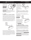
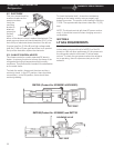
5.9 LOWER CIRCUIT BOARD
RM7030 (Product No. 921890201 & 921890301)
The circuit board controls all modes of operation.
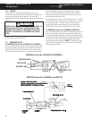
A. DC VOLTS
THESE PROCEDURES MUST BE FOLLOWED IN
SEQUENCE AND AT THE PROPER TERMINALS OR
DAMAGE TO THE BOARD WILL RESULT.
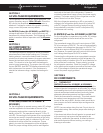
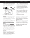
Before any checks are to be done, be
sure proper DC volts are to the board.
Measure volts between yellow terminal
on the 6-pin connector (positive [+] lead
from meter) to green terminal on 6-pin
connector (negative [] lead from
meter). Voltage should be the same as
at the positive (+) and negative ()
terminal block. If not, check the fuse and wiring.
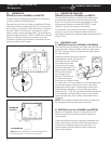
With main ON/OFF switch on display panel in ON
position:
Check for DC volts between terminal 3 (red wire), ()
negative and terminal 5 (green wire) and terminal 1
(black wire). If there is no voltage, the ON/OFF
switch on upper circuit board is defective. Replace
the upper circuit board. If voltage is present, the ON/
OFF switch is good.
Next, do the same voltage test at the lower circuit
board. Negative () plug 1, terminal 5 (red wire), to
plug 1, terminal 1 (green wire) and plug 1, terminal 3
(black wire). If there is no voltage and you had
voltage on previous test, the cable assembly is
defective and you must replace it. If voltage is
present, the ON/OFF switch on the upper circuit
board and cable assembly is good.
YEL L OW
GREEN
6
PIN