


16
DOMETIC® RM7030/RM7732
Refrigerators
DIAGNOSTIC SERVICE MANUAL
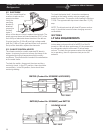
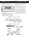
C. GAS OPERATION
THESE PROCEDURES MUST BE FOLLOWED IN
SEQUENCE AND AT THE PROPER TERMINALS OR
DAMAGE TO THE BOARD WILL RESULT.
Before you check the circuit board for gas operation,
verify these components are good:
Igniter (Sec 5.5A) High Voltage Cable (Sec. 5.6A)
Electrode (Sec. 5.11) Solenoid (Sec. 5.4A)
Upper Circuit Board (Sec. 5.8A to 5.8I)
Thermostat (Sec. 5.1)
Also be sure NO voltage is present at the
IGN lock terminal, and delay mode is not
activated. First, check that voltage in
excess of 10.5 volts is between the yellow
terminal on the 6-pin connector (positive
[+] lead from meter) to the ground strip
(negative [] lead from meter). If less than
10.5 volts, correct wiring and/or power
source problem.
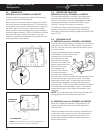
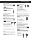
Next, check for the pulse voltage from the igniter at
the orange terminal on the 6-pin connector (negative
[] lead from meter) and the ground strip (positive [+]
lead from meter). If there is no signal voltage, check
the igniter (see Sec. 5.5A) and the orange wire and
connections. If signal voltage is present, next check
YEL LOW
6
Pin
ORANGE
6
Pin
for voltage on the solenoid wires at the
circuit board. Positive lead from meter to
the gray wire and negative lead from the
meter to the black wire. If voltage is 9.5
volts or more, the circuit board is good. Do
not replace. If no voltage is present, replace
the circuit board.
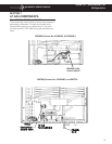
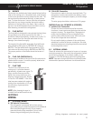
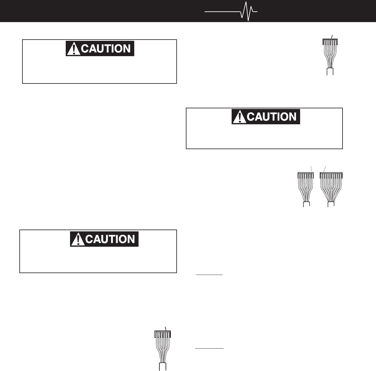
D. DC VOLTS TO UPPER CIRCUIT BOARD
THESE PROCEDURES MUST BE FOLLOWED IN
SEQUENCE AND AT THE PROPER TERMINALS OR
DAMAGE TO THE BOARD WILL RESULT.
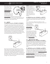
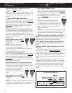
This check is to determine if the
lower circuit board is providing
voltage to the upper circuit board.
Measure between the brown
terminal on the 10-pin connector
(positive [+] lead from meter) to
the blue terminal on the 7-pin
connector (negative [] lead from
meter). A voltage reading indi-
cates the circuit board is good. If
no voltage is present, replace the circuit board.
NOTE: Before changing the circuit board, be sure all
troubleshooting steps have been followed.
BROWNBLUE
10 Pin7 Pin
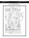
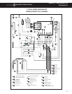
RM7030 (Product No. 921890401) & RM7732
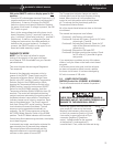
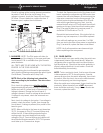
E. DC VOLT: ALL TESTS ARE TO BE DONE WITH
THE REFRIGERATOR IN THE COOLING MODE.
Before any checks are made, make sure the board
is receiving proper DC volts. Measure volts between
terminal J4 and the ground strip. Voltage should be
the same as at the positive (+) and negative (-) on
the terminal block. If not, check for loose connec-
tions.
F. AC MODE: NOTE: The PAL tester will allow for
proper testing of the integrity of the upper and lower
circuit boards. PAL is available from your Dometic
parts distributor.
ALL TESTS ARE TO BE DONE WITH THE REFRIG-
ERATOR IN THE COOLING MODE.
For AC heating element operation, check that
incoming AC voltage is present at terminals J5 and
J6 on the circuit board. If voltage is below 100 volts,
see Sec. 2.
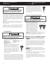
B. AC OPERATION
THESE PROCEDURES MUST BE FOLLOWED IN
SEQUENCE AND AT THE PROPER TERMINALS
OR DAMAGE TO THE BOARD WILL RESULT.
For AC heating element operation, check that voltage is
present between the large black and large white wire at
the circuit board. If voltage is below 100 volts, the circuit
board will select another mode. If voltage is above 100
volts, check that AC volts are present at the heating
element connection. If no voltage is present, change the
circuit board.
NOTE: Before installing a new circuit board, correct the
cause of the failure, most likely it is the heating ele-
ments or wiring.
If voltage is present, DO NOT CHANGE THE CIRCUIT
BOARD. Check the following components: heating
elements, upper circuit board, thermostat and wiring.