


21
DIAGNOSTIC SERVICE MANUAL
DOMETIC® RM7030/RM7732
Refrigerators
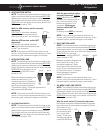
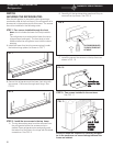
7.4 BURNER
The burner is a slotted metal tube located below the flue
tube on the cooling unit. It should be level, and the slots
in the burner should be directly below the flue tube. The
burner should be cleaned periodically, at least once a
year. To clean the burner, remove from the refrigerator
and check for any foreign residue that could cause a
deflection of the gas flow or the flame. Next, soak the
burner in an alcohol based solvent and allow to air dry.
After cleaning, reinstall in the refrigerator.
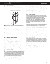
7.5 FLUE BAFFLE
The flue baffle is designed to concentrate the heat (from
the gas flame) at a certain area of the flue tube. It
should be cleaned periodically, at least once a year. To
clean, remove from the flue tube and check for any
damage, then clean thoroughly.
The length of the flue baffle assembly (flue baffle and
wire) should be 39 inches on RM7030; 40 inches on
RM7732. The flue baffle itself should measure 13/16
inch wide and 6 inches long on RM7030 and RM7732.
The proper position of the baffle above the burner is 1
inch.
7.6 FLUE CAP (RM7030 ONLY)
The flue cap is located at the top of the flue tube and is
attached with a screw. It must be properly attached or
flame outage could occur.
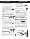
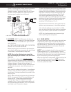
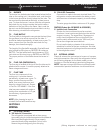
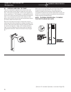
7.7 FLUE TUBE
The flue is a component of the
cooling unit. It must be cleaned
periodically, at least once a year. To
clean, remove flue cap and flue
baffle, then cover the burner and
clean by using a flue brush, Domet-
ic Part No. 0151404001. If the flue
tube becomes coated with scale or
residue from combustion of LP gas,
the efficiency of gas operation
decreases.
NOTE: After cleaning be sure to
reinstall the flue baffle and flue cap.
FLUE
CAP
FLUE
TUBE
SECTION 8
WIRING
8.1 EXTERNAL WIRING
A. 120 Volts AC Connection
The refrigerator is equipped with a three-prong
(grounded) plug for protection against shock hazards
and should be plugged directly into a properly
grounded three-prong receptacle. Do not cut or
remove the grounding prong from this plug.
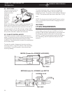
B. 12 Volt DC Connection
Connection is made to the main terminal block. The
refrigerator must be connected to the battery circuit
with two wires of adequate capacity to avoid voltage
drop.
The wire gauge should be a minimum of 14 gauge.
RM7030 (Poduct No. 921890201 & 921890301)
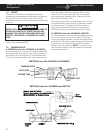
C. Ignition Lock Connection
In order for the circuit board to perform certain
functions, it must receive a signal when the vehicle
engine is running. The signal wire (16 gauge mini-
mum) should originate at the run terminal of the
ignition switch and connect to the "IGN Lock" posi-
tion on the refrigerator terminal block.
Do not use the body or chassis of the vehicle as a
substitute for either of the two conductors. No other
electrical equipment or lighting should be connected
to the refrigerator circuit.
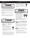
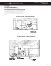
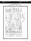
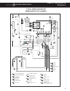
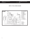
8.2 INTERNAL WIRING
Check all wires at the connectors to be sure of a proper
and tight connection. Also verify the refrigerator is wired
per the wiring diagram for the exact model you are
working on. See the following typical wiring diagrams.
NOTE: Improper wiring at the lower circuit board could
cause erratic operation and lower circuit board failure.
(Wiring diagrams continued on next page)