


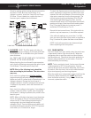
13
DIAGNOSTIC SERVICE MANUAL
DOMETIC® RM7030/RM7732
Refrigerators
B. AES FUNCTION SWITCH
NOTE: The following checks should be made on the
upper circuit board and harness assembly BEFORE
replacing the upper circuit board or wiring harness.
The checks are to be done with the wiring harness
REMOVED from the lower circuit board, and the ON-
OFF switch turned to "ON".
With the AES function switch manually
depressed:
CONTINUITY should be indicated
between the blue terminal and the
black terminal on the 7-pin connector.
With the AES function switch NOT
depressed:
NO continuity should be indicated
between the blue and black terminals
on the 7-pin connector.
NOTE: If the check on AES function switch is not
correct, verify the wire harness has continuity. If wire
harness is good, replace the upper circuit board.
C. AES FUNCTION LAMP
NOTE: The following checks should be made on the
upper circuit board and harness assembly BEFORE
replacing the upper circuit board or wiring harness.
These checks are to be done with the wiring harness
REMOVED from the lower circuit
board and the ONOFF switch
turned to "ON".
Measure resistance between the
brown terminal on the 7-pin
connector (positive [+] lead from
meter) to the brown terminal on
the 10-pin connector (negative
[] lead from meter). The proper resistance is
approximately 26,000 ohms.
NOTE: If the check on the AES function lamp is not
correct, verify the wire harness has continuity. If wire
harness is good, replace the upper circuit board.
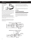
D. GAS FUNCTION SWITCH
NOTE: The following checks should be made on the
upper circuit board and harness assembly BEFORE
replacing the upper circuit board or wiring harness.
The checks are to be done with the wiring harness
REMOVED from the lower circuit board and the ON-
OFF switch turned to "ON".
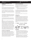
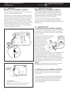
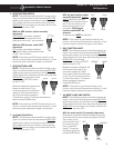
BROWNBROWN
10 Pin7Pin
BLACK
BLUE
7Pin
With the gas function switch
manually depressed: CONTI-
NUITY should be indicated
between the violet terminal on
the 10-pin connector to the
blue terminal on the 7-pin
connector. With the gas
function switch NOT de-
pressed:
A reading would NOT be indicated.
NOTE: If the check on gas function switch is not
correct, verify the wire harness has continuity. If wire
harness is good, replace the upper circuit board.
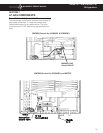
E. GAS FUNCTION LAMP
NOTE: The following checks should be made on the
upper circuit board and harness assembly BEFORE
replacing the upper circuit board or wiring harness.
These checks are to be done with the wiring harness
REMOVED from the lower
circuit board, and the ONOFF
switch turned to "ON".
Measure resistance between the
brown terminal on the 10-pin
connector (negative [] lead
from meter) to the white terminal
on the 10-pin connector (positive
[+] lead from meter). The proper
ohms resistance is approxi-
mately 26,000 ohms.
NOTE: If the check on gas function lamp is not
correct, verify the wire harness has continuity. If wire
harness is good, replace the upper circuit board.
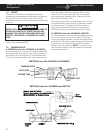
F. AC MODE LAMP AND SWITCH
NOTE: The following checks should be made on the
upper circuit board and harness assembly BEFORE
replacing the upper circuit board or wiring harness.
These checks are to be done with the wiring harness
REMOVED from the lower circuit board, and the ON-
OFF switch turned to "ON".
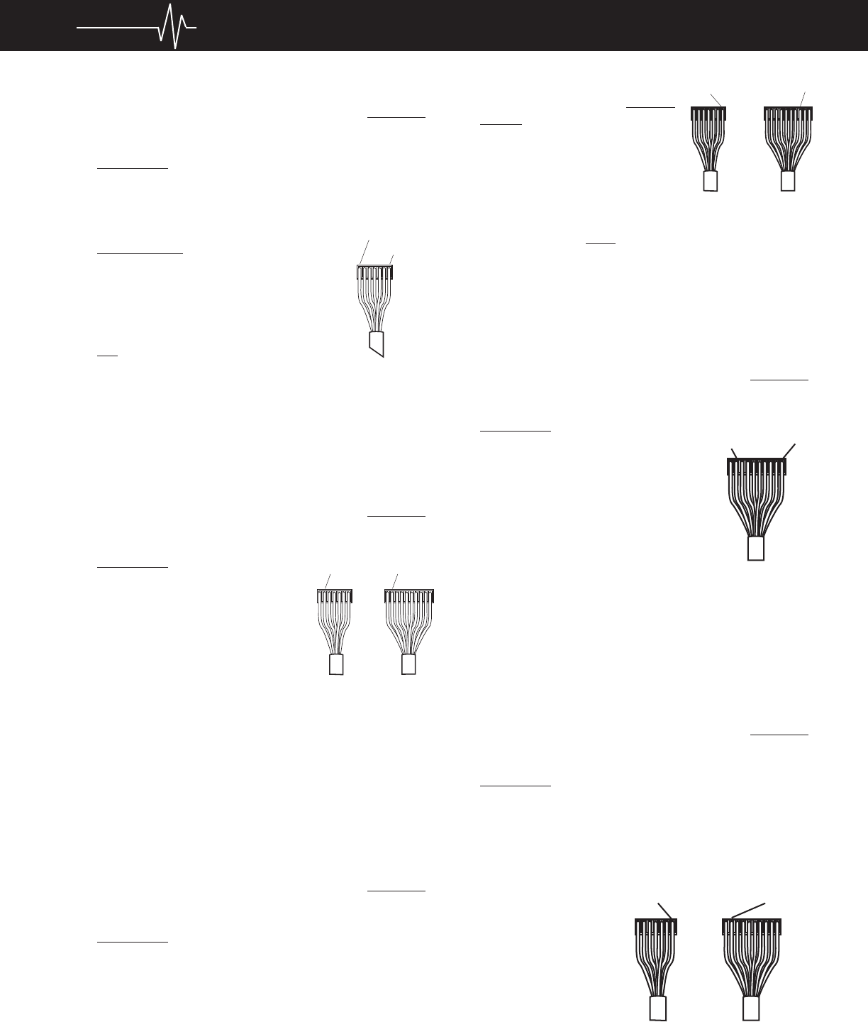
With the mode switch (?) manually depressed:
Resistance should be indicated between the brown
terminal on the 10-pin connector (negative [] lead
from meter) to the
red terminal on the 7-
pin connector (posi-
tive [+] lead from
meter). The proper
resistance is approxi-
mately 26,000 ohms.
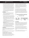
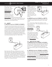
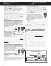
7PIN
10 PIN
VIOLET
BLUE
WHITE
BROWN
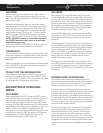
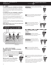
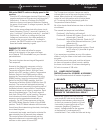
10 PIN
7PIN
10 PIN
RED
BROWN