


17
DIAGNOSTIC SERVICE MANUAL
DOMETIC® RM7030/RM7732
Refrigerators
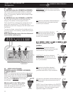
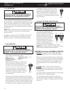
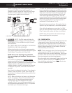
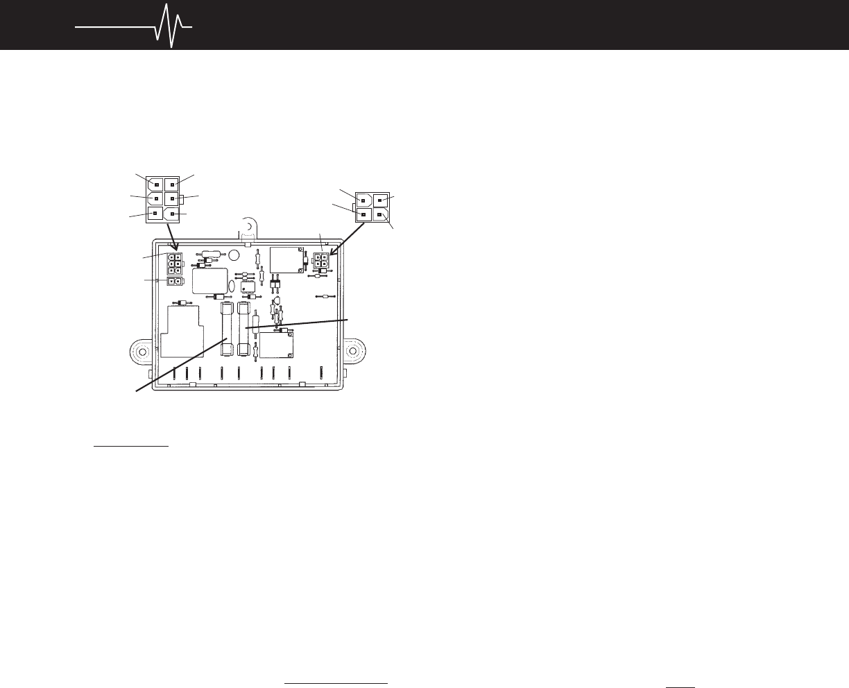
Check for voltage at the heating element connection
terminals J7 and J8 on the circuit board. If no
voltage is present, check the 5 amp AC and 3 amp
DC fuses. If fuse is defective, replace the fuse. If
fuses are good, replace the circuit board.
G. GAS MODE: NOTE: The PAL tester will allow for
proper testing of the integrity of the upper and lower
circuit boards. PAL is available from your Dometic
parts distributor.
ALL TESTS ARE TO BE DONE WITH THE REFRIG-
ERATOR IN THE COOLING MODE.
Before checking the circuit board for gas operation,
verify that the following components are good: Upper
Circuit Board, Thermistor and 3 Amp Fuse.
NOTE: Each of the following tests should be
done according to pin locations. The wire colors
may vary.
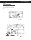
First, check for voltage during trial-for-ignition
(approximately 45 seconds) at Plug 3, Terminals 1
(white wire) and 2 (yellow wire) to the solenoid. If no
voltage is present, change the circuit board. If
voltage is present, check for voltage at the solenoid.
If voltage is not present, check the wires and con-
nections.
Next, check for voltage to the igniter. If no voltage is
present, check the wires. If good, then change the
circuit board. If voltage is present, this portion of the
board is good.
NOTE: When millivolts to the lower circuit board are
10 ± 3, the power to Plug 3, Terminal 4 (blue wire)
will be shut off. If flame extinguishes during the
cooling mode, the circuit board will not supply
voltage to Plug 3, Terminal 4 (blue wire) again until
the millivolts have decreased to 10±3. This process
could take up to 15 seconds or longer.
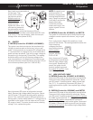
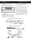
To check the flame sense circuit of the lower circuit
board, operate the refrigerator on GAS mode, then
measure the millivolts between J3 terminal and the
other wire connection from the thermocouple. The
millivolt meter should read between 25 to 35 milli-
volts with the gas flame burning. Next, turn the
manual shutoff valve to OFF and watch the millivolt
reading as it drops. Note the millivolt reading when
Plug 3, terminal 4 (blue wire) receives power. It
should be 10±3 millivolts or 7 to 13.
Repeat this test several times. If the igniter fails to
spark on any test sequence, it should be replaced.
If the millivolt readings vary more than 1 to 2 MV
from one test to the other when power is supplied to
Plug 3, terminal 4, replace the lower circuit board.
NOTE: Verify all connections are clean and tight
before replacing either component.
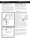
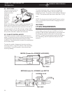
5.10 DOOR SWITCH
The door switch is an open switch when the switch arm
is depressed (interior light should be off). When the
refrigerator door is open the switch is closed (interior
light should be on). Check that the switch assembly is
properly aligned and that it is not broken. Check the
switch assembly for continuity.
NOTE: To do a continuity check, first be sure all power
is disconnected or OFF to the refrigerator. Second,
remove all wires from the switch assembly, then check
the switch. After the check, be sure the switch assem-
bly is wired properly per the wiring diagram.
When the switch arm is depressed, there should not be
continuity. When the switch arm is NOT depressed,
there should be continuity. If any of these checks are
incorrect, replace the switch.
P1
P2
P3
J1
J2
J3
J4
J5
J6
J7
J8
J1 0
3 AMP FUSE
FIVE
AMP
FUSE
Black 3
Open 2
Green 1
6 Brown
5 Red
Open 3
Blue 4
1 Whit
e
1 Whit
e
2 Yellow
4 Orange
or White
4 Orange
or White