26
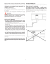
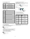
C.2.1 Basic system connection (accessory code F880048)
The printer can provide a printout of data obtained by the sensor
connected to the electronic board. For this,
connect the serial cable (screened) to the printer and the
appliance itself.
Set the printout interval (see parameter TPRN); and define the
type of report by means of the parameter “PRND”.
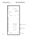
C.2.2 REPORT PRINTOUTS (fig.11 example of report
printout)
Reports are printed automatically when the appliance is switched
on.
The printout gives the data obtained by the electronic board
and indicates:
- the start date and time, repeated every 20 lines of temperature;
- the compartment temperature at preset intervals (user
parameter TPRN);
- a description of the type of alarm generated and the alarm
start and end time;
- defrost start and end time.
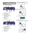
The Heavy Duty range refrigerated counters have been designed
with a modular structure. In this way the main components of
the appliance can be easily replaced.
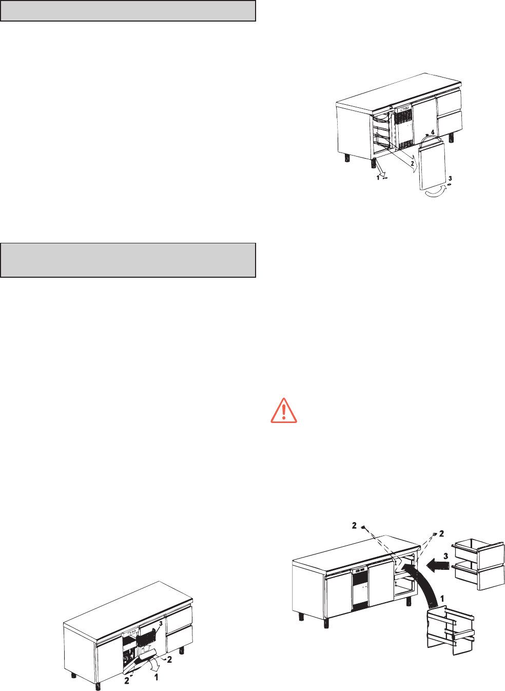
C.3.1 COOLING UNIT COMPARTMENT MODULARITY
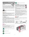
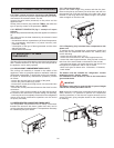
The cooling unit assembly is located in the middle of the
appliance in order to guarantee optimum ventilation inside the
refrigerated compartment. To access the cooling unit assembly,
for routine or extraordinary maintenance operations, proceed
as follows:
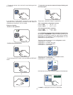
- remove the chromed cap in the middle of the panel;
- remove the panel middle fixing screw;
- remove the 3 control panel fixing screws, one central and two
lateral (right and left);
- remove the control panel then disconnect the wires from the
connectors;
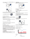
- loosen the 4 fixing screws located on the right and left side of
the counters, then remove the complete cooling unit assembly;
- in this way the unit is completely removed from the refrigerated
counter and routine maintenance operations can be carried
out quickly and easily.
C.3.2 REFRIGERATED COMPARTMENT MODULARITY
The refrigerated compartments can be easily customized,
therefore the structure with doors (inside food rack) can be
quickly replaced by that with drawers. The operations necessary
for customizing are given below.
C.2 HACCP CONNECTIONS (ACCESSORIES)
C.3 MODULARITY OF MAIN
COMPONENTS
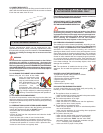
C.3.2.1 Reversing the door
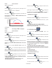
Remove the bottom hinge fixing screws and then the door.
Remove the plate on the bottom part of the door and refit it on
the opposite side. Shift the top hinge to the other side, place
the door on the hinge then fix the bottom hinge in the special
seats arranged on the other side.
C.3.2.2 Replacing fully insulated door compartment with
drawer unit
To replace the fully insulated door compartment (inside food
racks) with the compartment with drawer unit, carefully carry
out the following:
- remove the door (see point C.3.2.1);
- remove the food racks from the metal support structure;
- remove the metal support structure, lifting it a little in order to
take it out of the seat located on the bottom of the counter;
- insert the new drawer unit support structure, then secure it to
the appliance compartment and fix with 4 screws.
- there are 3 types of drawer units: 1/3 drawers; 1/2 drawers;
bottle holder.
The drawer units are available for “refrigerator” counter
models but not for “freezer” models.
For installation of the drawer kit, refer to the instructions
given inside the kit.
IMPORTANT:
The drawers must only be used with GN 1/1 pans of height
2.56"/65 mm, already included in the kit.
Note: As the fully insulated door compartments are modular and
easily removed, it is possible to optimize all compartment
cleaning operations. In fact the rack support structure can be
quickly removed, giving complete access to the compartment
for cleaning.


