


10
11
CABLING
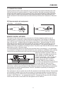
LF-CONNECTION CORDS
Choosing balanced cables (two conductors for the audio signal plus separate shielding mesh) with
XLR-type connectors is recommended for LF-signal connection. Although connecting unbalanced
cables to the power amplier inputs is possible as well, using balanced cabling is always preferable.
A great number of today’s audio appliances employ balanced outputs. With balanced cabling, the
shield connects all metal enclosure parts and thus efciently eliminates the introduction of noise and
hum.
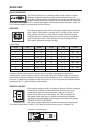
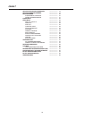
XLR-type connector pin-assignment
XLR (male) XLR (female)
REMOTE CONTROL NETWORK
The network of the remote power amps is based on the CAN-bus standard, which for years is
especially popular in automotive, industrial and security applications. The CAN-bus is a balanced
serial interface for command and data transmission. Controlling the power ampliers is performed
from a PC with IRIS – Intelligent Remote & Integrated Supervision – software installed. The UCC1
USB-CAN Converter serves as interface between the PC and the CAN-bus. Connecting up to 100
power ampliers per CAN-Bus with a maximum total cable length of 1,000 meters is possible. An
additional CAN-bus is needed for controlling more than 100 power amps while the IRIS software allows
administering a total of 250 power amps.
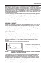
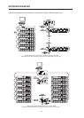
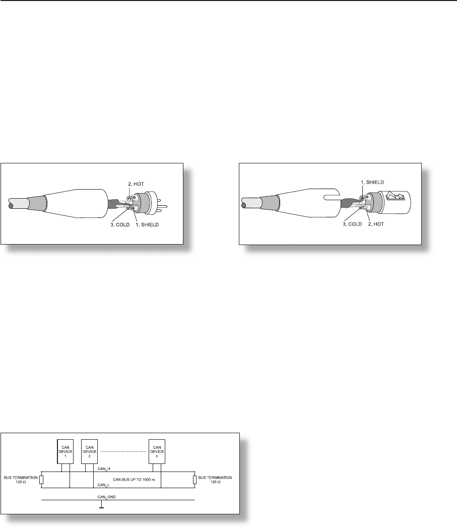
The network topology used by the CAN-bus is the so-called “bus or line topology”, i.e. all participants
are connected via a single two-wire cable (Twisted-Pair cable, shielded or unshielded) with the cabling
running from one participant on the bus to the next, allowing unlimited communication among all
appliances included. In general, it does not
matter whether a participant on the bus is a
power amplier or a UCC1 USB-CAN
converter, so that both – UCC1 and the PC
as well – can be inserted at any position.
Incorporating several UCC1 and PCs
on a single CAN-bus is also possible. A
total of up to 100 appliances can be operated
on a single CAN-bus. Since the CAN-
interfaces of all appliances are galvanically separated from the rest of the circuitry, network cabling
also carries a common ground conductor (CAN_GND) ensuring that all CAN-interfaces in the network
are connected to a common ground potential. The UCC1 provides the possibility for switching the
CAN-ground to circuit-ground.
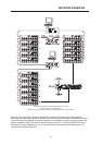
Each participant on the bus system has two RJ-45 connectors for the Remote CAN-bus. These sockets
are connected in parallel to serve as input and output (for connecting through) for the data transfer of
the remote-network. The CAN-bus has to be terminated at both ends using 120 terminator plugs, two
of which – CAN-TERM 120 – are supplied with the UCC1. Connect one of these to the RJ-45 socket
of the rst and the other to the socket of the last appliance on the CAN-bus.