


8
9
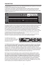
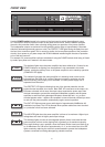
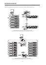
REAR VIEW
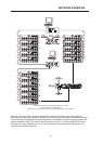
RS-232 INTERFACE
The RS-232 interface is for connecting media control systems as well as
building management systems providing control and monitoring of all
parameters. Communication is established via an easily to implement ASCII-
protocol allowing trouble-free integration of Remote Ampliers in media and
touch panel control systems. For a programmer’s guide and complete protocol description, please re-
fer to the documentation accompanying the IRIS software.
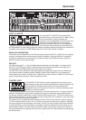
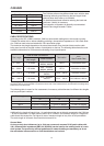
ADDRESS
The address selection switch allows setting the amplier’s network address,
which, within a CAN-network, can range from 01 to 250 (FA hex). Caution:
Each address may exist only once within a network. Otherwise network
conicts might occur. Address setting has to be performed in hexadecimal
code. The selection switch LOW represents the low-value digit while the
HIGH-switch represents the high-value digit.
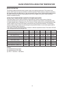
Adress-Table:
HIGH LOW Adress HIGH LOW Adress
0 0 Stand-alone 8 0 ... F 128 ... 143
0 1 ... F 1 ... 15 9 0 ... F 144 ... 159
1 0 ... F 16 ... 31 A 0 ... F 160 ... 175
2 0 ... F 32 ... 47 B 0 ... F 176 ... 191
3 0 ... F 48 ... 63 C 0 ... F 192 ... 207
4 0 ... F 64 ... 79 D 0 ... F 208 ... 223
5 0 ... F 80 ... 95 E 0 ... F 224 ... 239
6 0 ... F 96 ... 111 F 0 ... A 240 ... 250
7 0 ... F 112 ... 127 F B ... F reserved
Address 0 (00 hex, factory-pre-set) ensures that the amplier is separated from the remote
communication, so that it does not appear in the system set-up even though it might be connected
to the CAN-bus. When the amplier is powered-on with its address set to “0”, all internal parameters
are set to “0” respectively to bypass and the routing is set to 2-in-2. In that case the amplier behaves
absolutely linear, i.e. signal processing is deactivated.
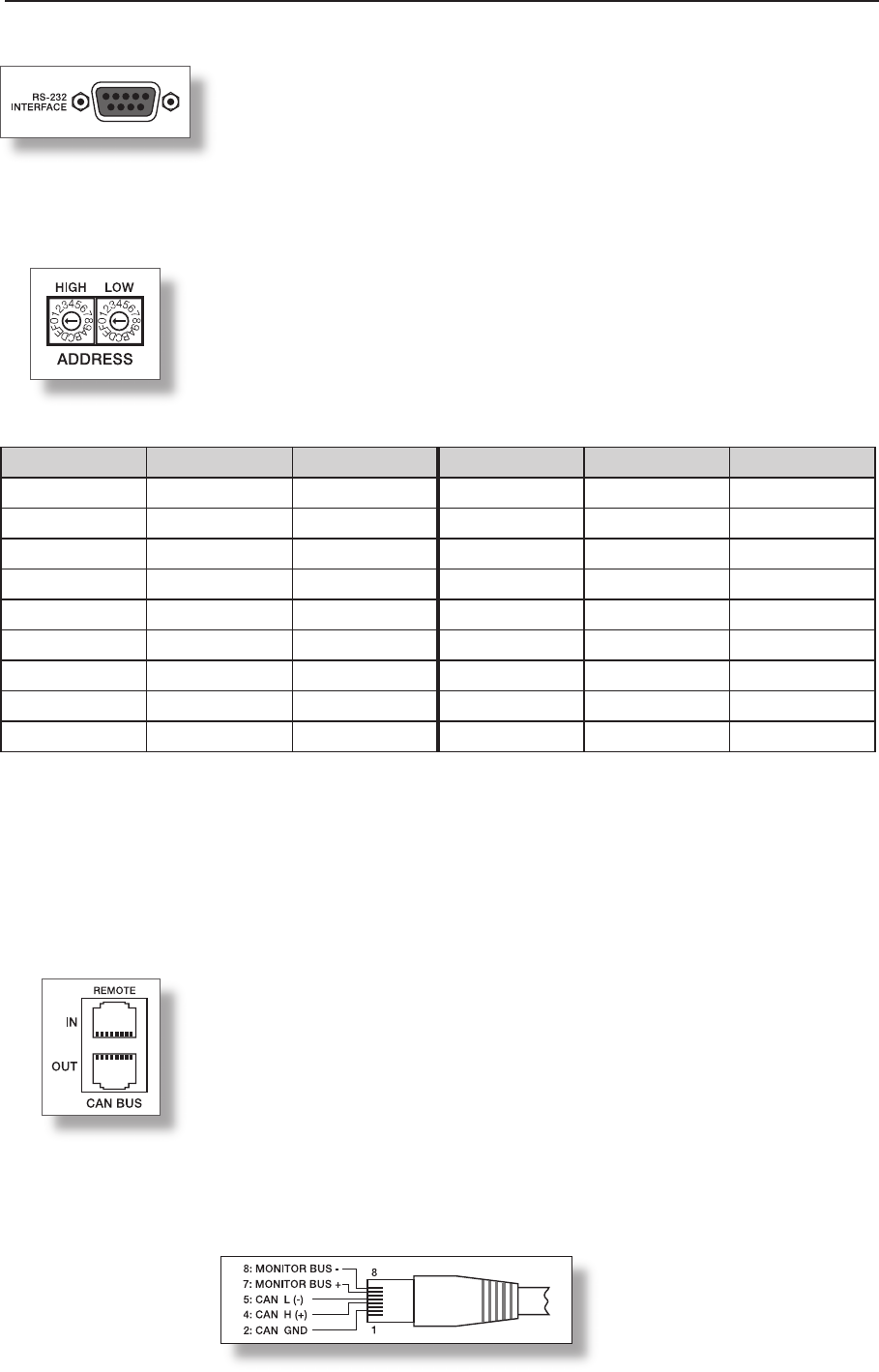
REMOTE CAN BUS
Each amplier employs two RJ-45 sockets for Remote CAN-bus connection.
The sockets are parallel connected and serve as input as well as for
connecting through of the Remote network. Common RJ-45 patch
cables can be used for rack-shelf cabling. The CAN-bus needs to be
terminated at both ends using a 120ohms termination plug. Detailed
guidelines concerning cabling and bus length are provided in the chapter
“REMOTE CONTROL NETWORK”.
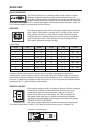
Both RJ-45 sockets additionally carry the balanced audio monitor signal.
The nominal output level is +6dBu (1.55V) while the maximum output level is +21dBu (8.7V).
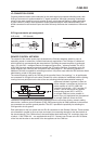
Connector Pin-Assignment:
(View of Contacts)