


6
7
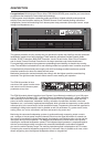
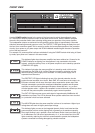
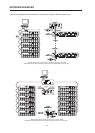
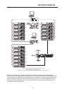
REAR VIEW
INPUT A / INPUT B
The inputs INPUT A & INPUT B are electronically
balanced offering an input sensitivity of +6dBu (1.55V)
for direct connection of mixing consoles, etc.
Connection can be established via the XLR-type input
connectors or the supplied screw-on connectors,
which are connected in parallel. The pin-assignment
of the XLR-type input connectors is according to the
IEC 268 standard. In case oating inputs are needed, retrotting optionally available input transformers
is possible. One extension-kit NRS 90208 (Order-No. 121 641) per channel is needed.
PARALLEL CONNECTION
Connection can be established via the XLR-type input connectors INPUT A / INPUT B or the supplied
screw-on connectors which are connected in parallel. In addition, using the PARALLEL-connectors
provides the possibility for connecting the input signal through to feed additional power ampliers,
without the need for extra splitter-cables.
DSP OUT
The DSP output signal – i.e. the post-digital-signal-processing-unit audio signal – is present at the
DSP OUT. The DSP output signal is simultaneously fed to the power amplier output stage and is
correspondingly amplied present at the power amp’s main outputs.
The DSP OUT can be utilized for feeding the digitally processed audio signal from the RCM-24 Re-
mote Control Module to additional power ampliers (without DSP-module); e.g. for increasing the
overall output power. With a nominal level of +6dBu and a maximum level of +21dBu (8.7V) the output
signal is electronically balanced. Output impedance is 100Ω.
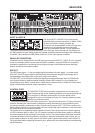
CONTROL PORT
The CONTROL PORT offers two freely programmable control inputs and
control outputs as well as the reference connections for ground potential and
+5V. Using the PC Windows software IRIS, the control inputs can be
congured and serve for instance for Power-On / Stand-by switching, preset
switching or parameter control.
The two control contacts IN1 / IN2 are internally set to +5V (open) via pull-up
resistors. Activating the control inputs is possible by closing the contacts to ground potential (pin 3)
via external switches, pushbuttons or relays. The two control outputs OUT1 / OUT2 are carried out as
Open Collector Outputs. In non-active state (Off) they provide high ohmic resistance. In the active state
(On) these outputs are connected to ground.
The outputs serve for signalling internal operational states. They can be used for the direct triggering
of LEDs, indication lights or relays. The +5V reference connector provides power supply for externally
connected appliances with amperage of maximally 100mA. The control outputs allow signal indication
of operational states (critical temperature, exceeding or decline of dened limit values, faults, etc.) at
central operator desks or to other systems (re alarm system, general alert system) even without PC.
For further detail about conguring the control ports, please refer to the documentation accompanying
the IRIS software.