


ELECTRIC COOKTOP
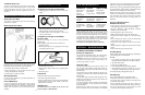
Surface Elements
Controls
Control knobs must be pushed
in before turning them to a
setting.
They can be set anywhere
between MAX and MIN.
The controls for the surface
elements provide infinite heat
settings. The numbers on the dial
serve as a reference. The control can be turned to any
setting to provide the exact heat required.
NOTE: The “Push to Turn Safety Control Knobs” on the
range are designed for child safety and to prevent
accidental operation.
Before using your glass cooktop for the first time: turn
the elements on MAX without a pan for 5 to 8 minutes
or until smoking stops. This smoking is normal and
non toxic.
High Speed Radiant - Electric Top Burners
Consists of a set of special RADIANT HEATER coils
embedded in thermal insulation. The element is designed for
fast heat response. You can see it light up almost
immediately.
Each element is fitted with a thermal limiter to ensure the
ceramic glass does not exceed the maximum SAFE
operating temperature. You may notice the element going on
and of
f a number of times during use. This is a normal
occurrence.
To maximize the efficiency of this type of element we
suggest you use it similarly to your previous burner. Turn to
maximum until the desired temperature is reached, then turn
it down to the setting that best maintains the desired heat.
Hot Lights
Hot lights are provided in the glass of all smooth top ranges.
Light glows when a burner becomes hot and shuts off when
the burner has cooled.
Controls
The radiant heating elements are controlled b
y a commonl
y
used Inf
inite Heat Switch that w
orks on the principle of
percent on, percent of
f. For example, when the switch is
turned to the medium setting, the element will be on only
50% of the time. Because of the fast heat-up with these types
of elements, you will notice the units switching on and off.
Cookware
The best cooking results and the most economical use of
electricity will be achieved by using smooth, flat-bottom
p
ans. Pans should be at least the same size or slightly
larger than the cooking area. Ceramic cookware suitable
for stovetop cooking may be used. If pans smaller than the
size of the heating element are used, care should be taken
as the handles may get hot.
Built into each element, is a safety device which protects the
element from overheating. If using pans which are not ideal,
for example concave or convex bottom pans with shiny
bases, or those with ridged or grooved bottoms, the thermal
limiter can cause the element to switch off and on during
cooking, which means that food will take longer to cook.
Very thin, badly dented, and distorted pans with uneven
bottoms should not be used.
Pans with very shiny or reflective bottoms should not be
used.
Never place utensils with a skirt (e.g. a wok) on the heated
area.
Pans should not have rough bottoms. Do not slide pots on
the ceramic glass cooking surface, as this may mark or
scratch the cooktop.
If pans with aluminum bottoms are slid across the cooking
surface, metal marks could result. Such marks are easily
cleaned with any non-abrasive stainless steel cleaner,
provided they are removed immediately and not allowed to
bake onto the surf
ace.
Any guidelines or recommendations given by the
saucepan or cooking utensil manufacturer should be
followed.
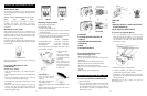
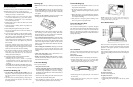
SELECTION & USE OF POTS & PANS
Flat Bottoms
Thick, flat bottoms absorb and distribute the heat from the
element more e
venly. Thin, uneven bottoms waste energy
and create hot spots that may burn the food onto
cookware.
Glass cooktops require heavy gauge flat bottom pans for
best cooking results.
Check flatness with a ruler or straight edge. See figure 7.
Figure 7
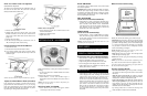
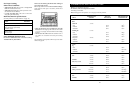
Pot Diameter
Select element to match pan diameter. The pot should be
slightl
y lar
ger than the element to obtain best ener
gy
usage, and avoid spillovers flowing directly onto element.
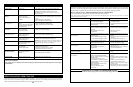
• H or 9 – To start foods cooking and to bring foods
to a boil.
• 8-7 – To hold a rapid boil.
• 6-5 – To fry foods.
•
4
– To cook large amounts of vegetables
• 3-2 – To keep food cooking after starting it
on a lower setting.
•
L – To keep foods warm until ready to serve.
7
Location
If possible, the range should be located to avoid the main
“traffic path” through the kitchen or where an open door
might block a passageway or create an awkward working
situation. If possible, it should be so located where cabinet
working space is available on either side. Drafty locations
should be avoided to prevent gas burner outage and poor
air circulation.
Temperatures
To cook, you must have heat. Some parts of the range are
therefore going to get warm or even hot. Consider this in
choosing a range location. Do not leave children alone or
unattended near the range when it is in use. Let burner
grids and other surfaces cool before touching them or
leaving them where children can reach them.
Clearances
This range may be installed with adjacent surfaces
touching the base cabinets and the back flush with the back
wall. Models 1955 and 1956 gas ranges require a
CGA/AGA approved stainless steel gas flex line or a
flexible copper coil 1/2" in diameter and at least three feet
long so the range can be moved for service.
To eliminate the risk of burns or fire by reaching over
heated surface burners, cabinet storage above the range
should be a
voided. If overhead storage is unavoidab
le,
clearances between the cooking surface and unprotected
wood or metal overhead cabinets must be no less than
32".
The clearances on electric models betw
een the
cooktop and unprotected overhead cupboards is 30". This
distance may be reduced to 24" when the bottom wood or
metal cabinets are protected by not less than 1/4" thick
flame retarding millboard co
vered with not less than No.
28MSG sheet steel, 0.015" thick stainless steel, 0.024"
thick aluminum or 0.020" thick copper.
NOTE: Clearances specified to combustible construction
(walls and materials) are based on a temperature rise of
wood resulting from appliance operation. These clearances
are suitable for walls of studding, lath and plaster or other
types of combustible material which have a density of
20 lbs. per cu. ft. or more. No evaluation of clearances has
been made for low density cellulose, fibre board and
similar materials which have a density of less than 20 lbs.
per cu. ft., nor to plastic tiles or sheeting.
The maximum depth of upper cabinets installed above the
range is 13".
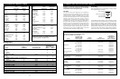
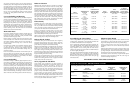
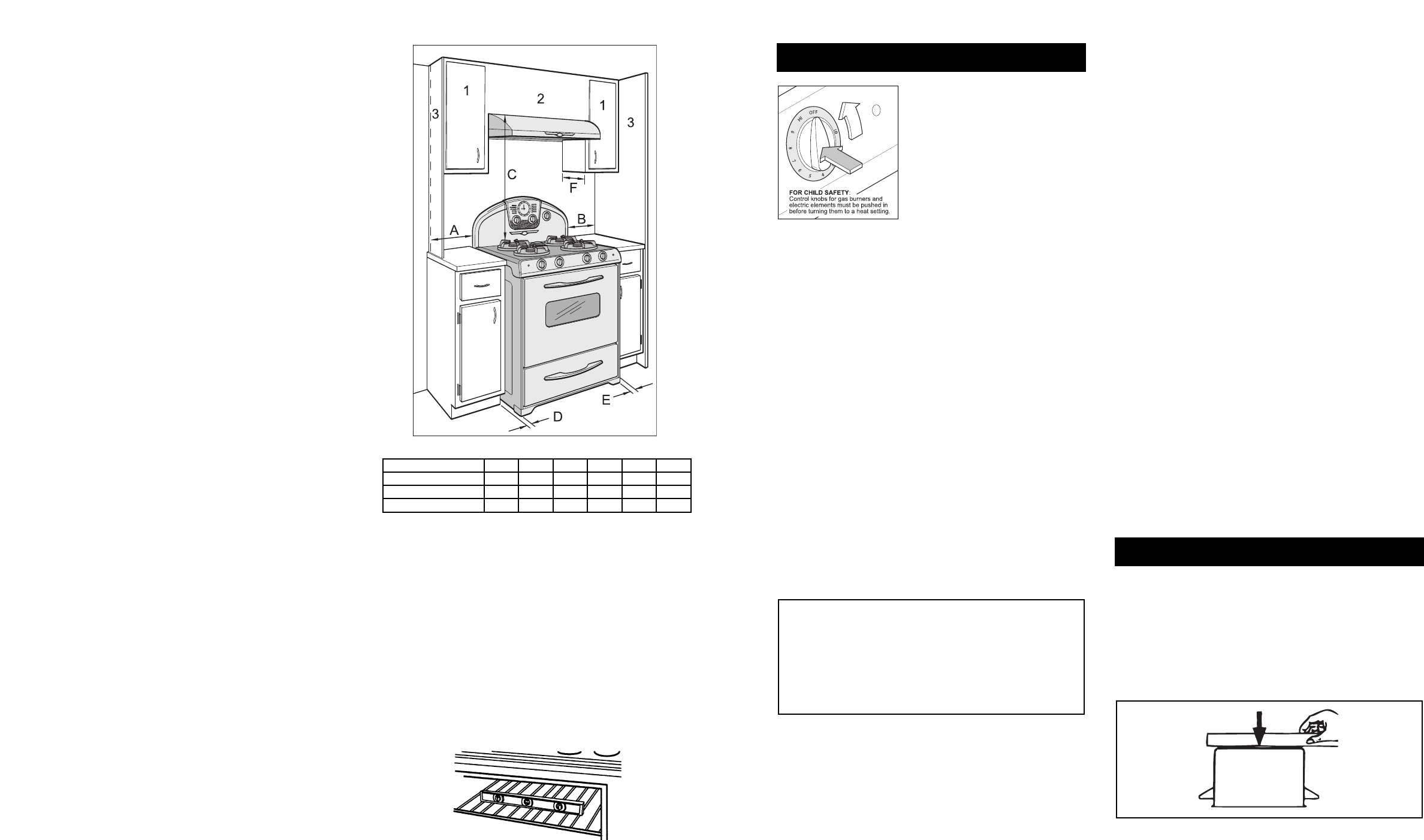
See the Minimum Clear
ances Chart
for electric and g
as
models below.
Exhaust Hood Dimensions – 30" W x 22" D x 6" H
Hood should be installed 28" to 30" from the bottom of
hood to the range cook top.
See Full Installation information
in Exhaust Hood Manual.
It is the responsibility of the installer to comply with the
installation clearances specified in this manual.
Cabinet Openings
This range will f
it into a 30 1/8" cabinet opening.
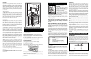
Leveling Your Range
Place rack in oven. Place level on rack, first side to side,
then front to back.
If the range is not level, adjust leveling legs up or down with
pliers or your fingers until range is level.
NOTE: Oven must be level for satisfactory baking
performance.
6
A B C D E F
All Model Electric 1954 0" 0" 30" 0" 0" 13"
Combo Model 1954 3" 3" 32" 0" 0" 13"
All Gas Model 1956 3" 3" 32" 0" 0" 13"
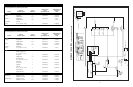
Minimum Clearances to Combustibles
1 = End of section of overhead cabinet
2 = Overhead center cabinet
3 = End wall or divider
Min.
Ht. 18”
Min.
Ht. 18”
Min.
Ht. 18”
Min.
Ht. 18”