


IP258
22
6.6 MAXIMUM % SOLIDS
To complete the calibration and to enable the system to automatically select the optimum frequency of operation., it
is necessary to set the maximum % solids that the system is required to measure.
In the AUTOCAL Menu, select ‘Max % Solids’ (P 160) and enter the value required.
If the maximum % solids are low then the system will choose the higher operating frequency (3.3 MHz). This will give
the best possible resolution. If the maximum % solids are higher than can be measured at 3.3 MHz then the system
will automatically select the lower frequency (1 MHz). The figure for the maximum % solids that can actually be
measured can be seen in MONITOR - DIAGNOSTICS - SENSOR – Max Measurable (D861)
The control unit is now calibrated and ready for operation.
6.7 CALIBRATION- Alternative calibration methods
Calibration is normally done via AUTOCAL. However, in special cases, if required, calibration can be done manually.
6.8 ZERO SETTING PROCEDURE
Firstly enable access using the “TOGGLE RUN” command in the Main menu. See section 5.2. Next, ensure that the
frequency of operation corresponds to the frequency of the sensor by checking parameter D860 located in
Monitor\Diagnostics\Sensor\Frequency. If necessary it can be changed. The relevant parameter is “Frequency” (P630)
located in Set up\ Engineer\. When the sensor is in “clear” liquid note the value of “Attenuation (D852) located in
Monotor\Diagnostics\ Sensor.
To complete the zero setting, enter this value in the appropriate “Zero ref” parameter, located in Calibration\ Manual
Entry\Zero ref.. “Zero ref A” (P120) is used for 1MHz sensors, “Zero ref B” (P121) is used for 3.3MHz sensors.
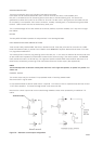
6.9 SPAN CALIBRATION/GRADIENT METHODS
There are three alternative ways of setting the gradient relationship between the measured attenuation and the %
solids displayed (See Graph shown in Figure2). It is recommended that if AUTOCAL is not used then the Initial Setup
should use Method 1: when later, figures are entered according to Methods 2 or 3, these automatically take priority
over an original Method I calibration.
The First alternative method uses previous Mobrey experience of slurries/sludges, and the slurry type is chosen by
name from a list. The MSM400 then uses the appropriate calibration line.
The Second alternative method uses actual site samples, and as such it is usually the most accurate calibration
method. When the MSM400 reading is stable, a sample of slurry is taken for Lab analysis, and the attenuation
measured at that time is recorded/entered in the MSM400 memory. Later the Lab result is also entered into a
different location in the MSM400 memory, and the microprocessor computes the relationship.
The Third alternative method uses a known mathematical value of attenuation versus suspended solids for the slurry
to be monitored from site experience on other tanks or other installations with the same sensor arrangement and
slurry.
6.10 CALIBRATION METHOD 1-SLURRY TYPE
Enter the CALIBRATION option on the MAIN MENU screen. Then ENTER ‘MANUAL ENTRY’. There are four
selections possible here. Select SENSOR\ Sensor Gap and enter the space between sensor faces, in mm. This tells
the MSM400 how big the sensor is, to relate it to memory figures of attenuation. Select SLUDGE TYPE (access
through CALIBRATION, MANUAL ENTRY, SENSOR menu) and for Method I calibration select one of the listed types
to suit the application. The unit will now work with this typical sludge calibration.
6.11 CALIBRATION-METHOD 2-SAMPLES
This Method of calibration offers the highest accuracy (and is used by AUTOCAL), since the MSM400 is set up based
on actual site sample analysis. It does therefore require quite a lot of site work in taking samples, and analysing the
solids %, to enter this later into the MSM400 microprocessor memory.